Bulk bag unloader with flow regulation

a flow regulation and bag unloading technology, applied in the field of bulk bag unloading with flow regulation, can solve problems such as inability to achieve flow regulation, and achieve the effect of enhancing flow regulation

Inactive Publication Date: 2006-07-13
WAHL RICHARD C
View PDF10 Cites 17 Cited by
  • Summary
  • Abstract
  • Description
  • Claims
  • Application Information

AI Technical Summary

Benefits of technology

[0017] The invention relates to a bulk bag unloader with a frame and means for suspending a bulk bag. An upwardly concave hopper is moveably mounted to the frame at a position below the suspended bulk bag. An outlet extends angularly from the lower end of the hopper. The outlet may be a tube, channel or trough and preferably is aligned at an angle of between 90° and about 45° to a gravitational axis

Problems solved by technology

Second, the vibrators generate longitudinal movement in the outlet substantially along the axis of the outlet.
Additionally, the combinati

Method used


Image

  • Bulk bag unloader with flow regulation
  • Bulk bag unloader with flow regulation
  • Bulk bag unloader with flow regulation

Examples


Embodiment Construction

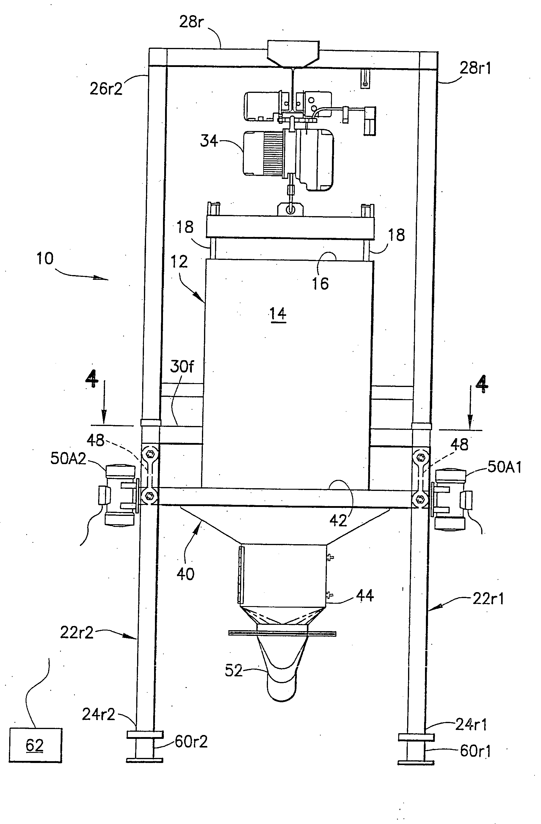
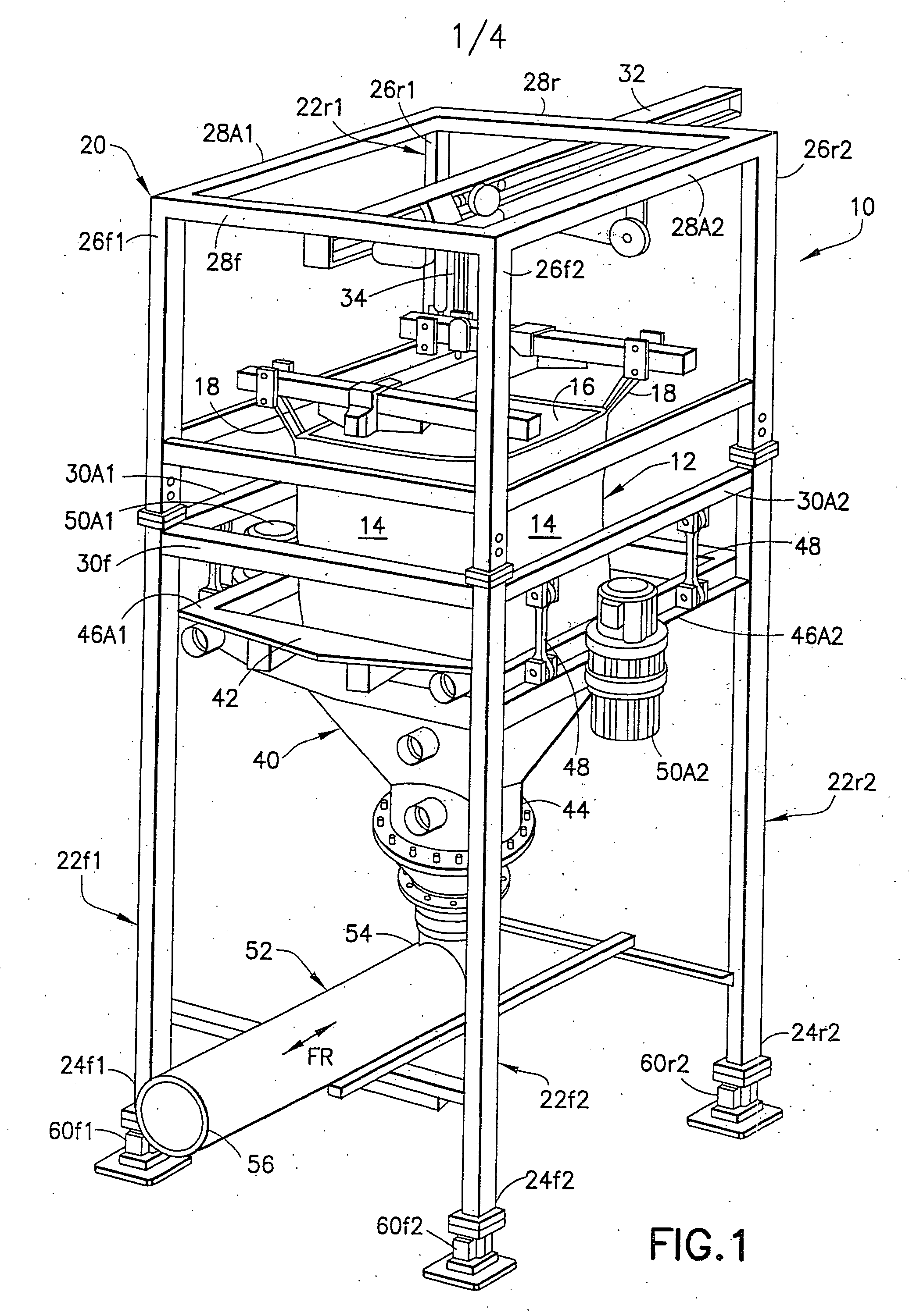
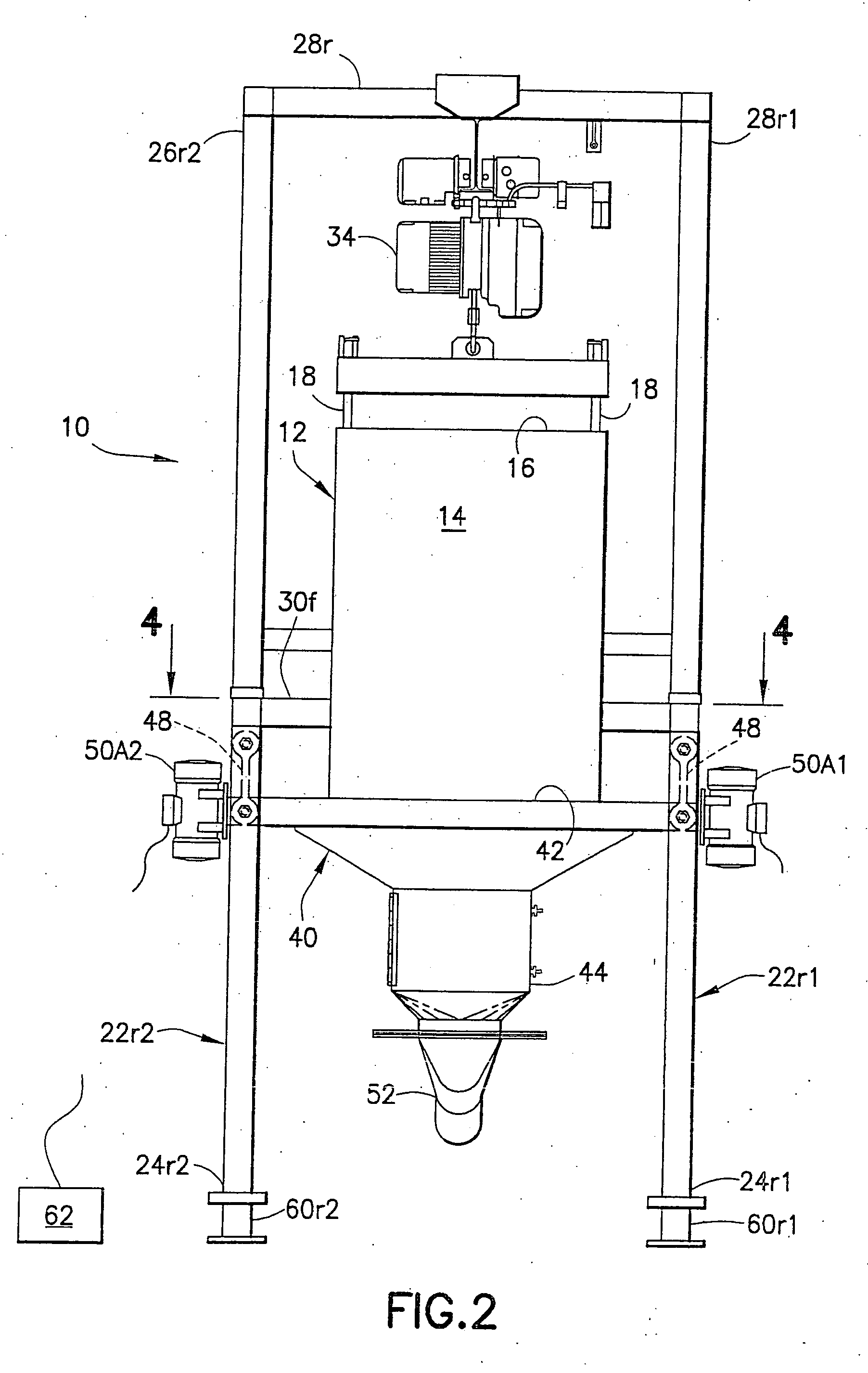
[0025] A bag unloader in accordance with the invention is identified generally by the numeral 10 in FIGS. 1-4. The bulk bag unloader 10 is intended for use with a bulk bag 12 formed from a strong flexible collapsible material. The bulk bag 12 is substantially rectangular when filled, as shown in FIG. 1. Thus, the bulk bag 12 has four substantially rectangular side walls 14, a top wall 16 and a bottom (not shown). The bottom is formed with a spout that can be opened to access the contents of the bulk bag 12. Four looped straps 18 extend from the top corners of the bulk bag 12 and permit the bulk bag 12 to be lifted by a fork lift truck and transported to the unloader 10. The bulk bag 12 illustrated herein is of prior art construction. Other configurations of bags exist and can be employed with the unloader 10.

[0026] The unloader 10 includes a generally rectangular frame 20 with four vertical support posts. More particularly, the frame 20 includes first and second front support posts...


PUM


Abstract

A bulk bag unloader includes a frame, a bag support, a hopper beneath the bag support and an outlet chute beneath the hopper. The hopper and the outlet chute are mounted to the frame for movement substantially in unison relative to the frame. Two vibrators are mounted respectively on opposite sides of the hopper and synchronized to generate vibratory movement substantially along the axis of the outlet chute. Thus, the vibrators function to achieve an efficient and continuous discharge from the bulk bag and employ the outlet chute to regulate or stop the flow in accordance with system requirements.

Description

[0001] This application claims priority on U.S. Provisional Patent Application No. 60 / 642,043, filed Jan. 7, 2005.BACKGROUND OF THE INVENTION [0002] 1. Field of the Invention [0003] The invention relates to an apparatus for achieving a controlled rate of discharge of a flowable particulate material from a bulk storage bag. [0004] 2. Description of the Related Art [0005] Many manufacturing processes, such as processes performed in the chemical, pharmaceutical and food industries, utilize particulate materials. The particulates may take the form of pellets, flakes, powders or fibers. The particulates often are purchased from an outside vendor or supplier and are transported to a site where the particulates will be processed. In other situations, the particulates will be subjected to an initial processing at one manufacturing location of a company and then shipped to another facility of the same company for further processing. [0006] Particulates traditionally were transported in rigid...

Claims


Application Information

Patent Timeline
IPC IPC(8): G01G13/00B65D88/66B67D5/06B67D7/06
CPCB65B69/0091G01G13/24G01G21/23
Inventor WAHL, RICHARD C.
Owner WAHL RICHARD C
Why Eureka
Try Eureka