Method and system for scatter correction in a positron emission tomography system

a positron emission tomography and scatter correction technology, applied in the field of positron emission tomography (pet) systems, can solve the problems of insufficient robustness of function-fitting methods, method not always performing satisfactorily for 3d pet acquisition, and bias estimation of activity distribution in patients

Active Publication Date: 2006-07-13
GENERAL ELECTRIC CO
View PDF6 Cites 33 Cited by
  • Summary
  • Abstract
  • Description
  • Claims
  • Application Information

AI Technical Summary

Problems solved by technology

Not rejecting the scatter events in the image reconstruction results in biased estimates of the activity distribution in the patient.
However, the method does not always perform satisfactorily for 3D PET acquisitions where scatter fractions are much larger.
However, for larger patients, the function-fitting methods are not robust enough as they over-estimate the scatter inside the object.
However, known model based scatter correction algorithms use many simplifying assumptions that can reduce the accuracy of the scatter estimation model.
Further, known model-based scatter correction methods are time consuming and involve intensive computations that are performed after the entire PET scan acquisition is completed because they use the measured emission data

Method used


Image

  • Method and system for scatter correction in a positron emission tomography system
  • Method and system for scatter correction in a positron emission tomography system
  • Method and system for scatter correction in a positron emission tomography system

Examples


Embodiment Construction

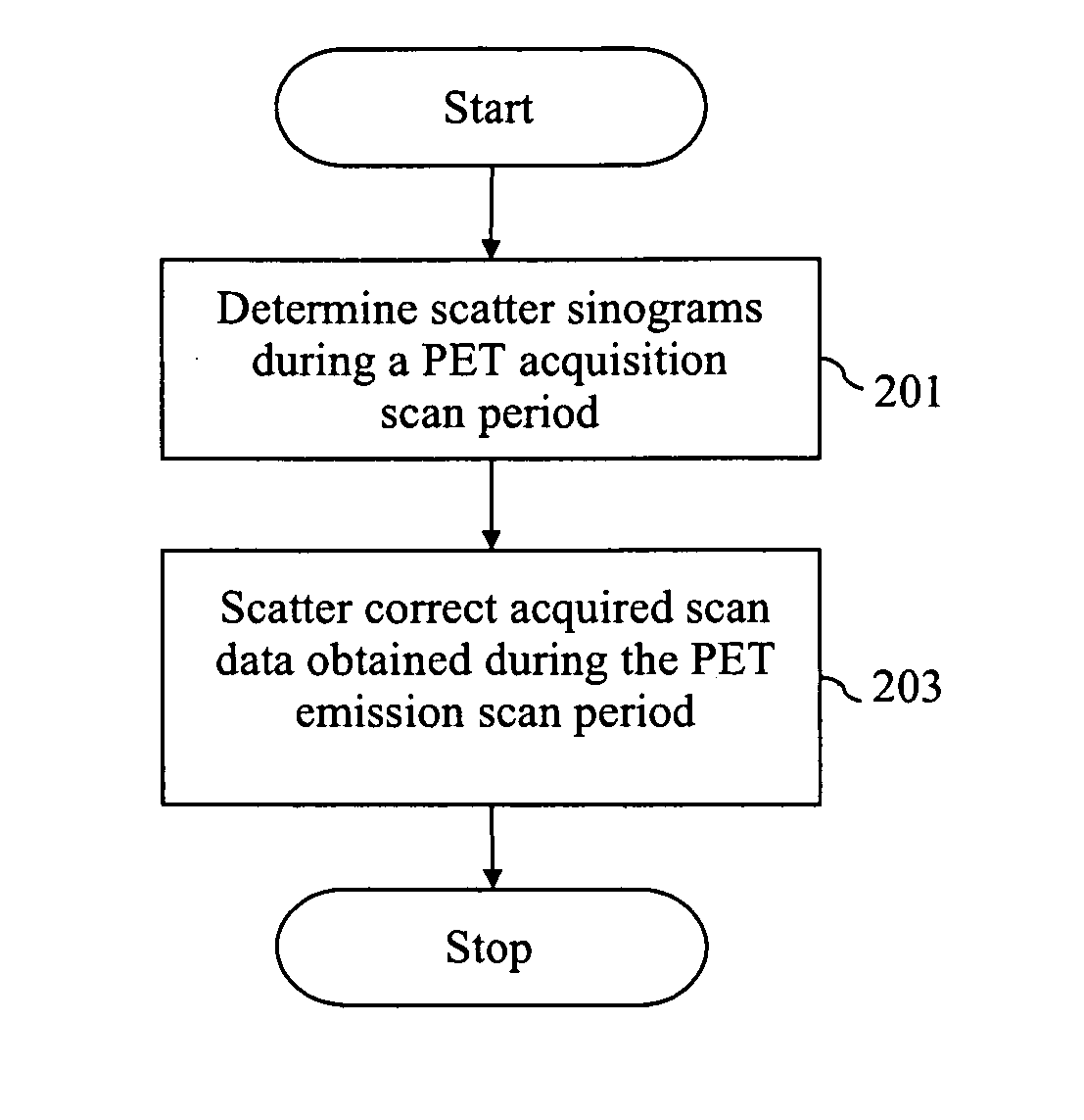
[0015] Various embodiments of the invention provide a method and system for reconstructing a PET image of a scanned object by computing a look-up table of scattered coincidence information as a function of spatial position in the object during the time period required for PET acquisition. This allows for correcting for scatter almost immediately, if not immediately, after the PET acquisition is completed. The computation of scatter look-up tables using, for example, modeling of the physics of scatter is performed during the PET acquisition scan period. The computed scatter look-up table enables a fast reconstruction of a PET image either by correcting the measured PET scan data for scatter prior to reconstruction or by using the scatter look-up table in an iterative image reconstruction loop and as described in more detail herein.

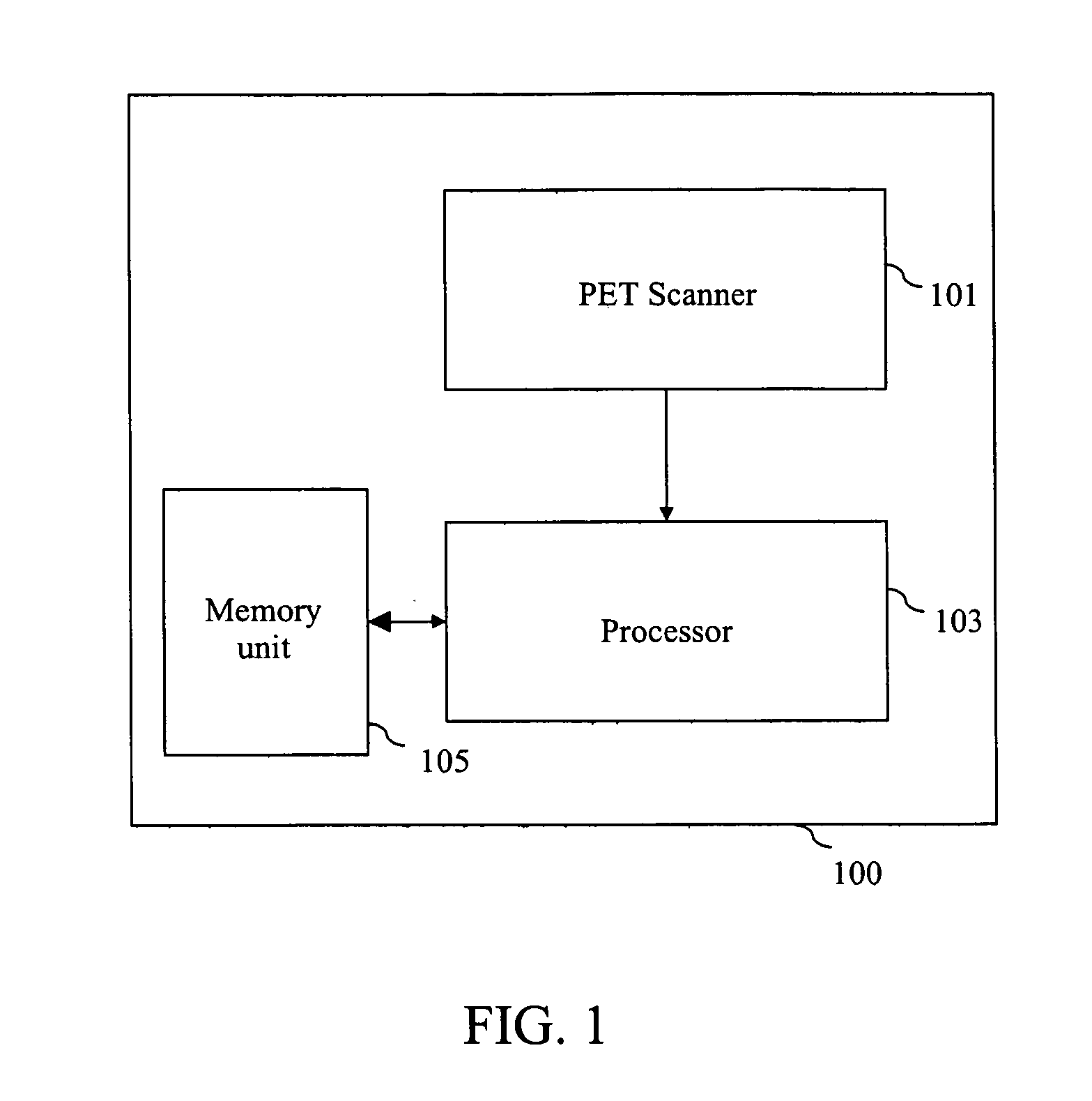
[0016]FIG. 1 is a block diagram showing a PET system 100 in accordance with an exemplary embodiment of the invention. In this embodiment, PET system 100 i...


PUM


Abstract

Methods and systems for providing scatter correction in a positron emission tomography (PET) system are provided. The method includes determining a look-up table of scatter sinograms during a PET acquisition scan period. The method further includes scatter correcting acquired scan data obtained during the PET acquisition scan period.

Description

BACKGROUND OF THE INVENTION [0001] The invention relates generally to positron emission tomography (PET) systems, and more particularly, to pre-computing a scatter sinogram look-up table during PET emission acquisition to correct for scatter. [0002] PET scanners typically generate images depicting the distribution of positron-emitting nuclides in patients. The positron interacts with an electron in the body of the patient by annihilation, and then the electron-positron pair is converted into two photons. The photons are emitted in opposite directions along a line of response. The annihilation photons are detected by detectors that are placed on both sides of the line of response on a detector ring. The image is then generated based on the acquired emission data that includes the annihilation photon detection information. [0003] A PET scanner typically includes a detector ring assembly including rings of detectors that encircle the patient. Coincidence detection circuits connect to t...

Claims


Application Information

Patent Timeline
Patent Type & Authority Applications(United States)
IPC IPC(8): G01T1/164
CPCA61B6/037G01T1/2985
Inventor MANJESHWAR, RAVINDRA MOHANJANSEN, FLORIBERTUS PHILIPPUS MARTINUS HEUKENFELDTSTEARNS, CHARLES WILLIAM
Owner GENERAL ELECTRIC CO
Why Eureka
Try Eureka