Vehicle radar sensor assembly

Active Publication Date: 2006-07-13
VALEO RADAR SYST
View PDF46 Cites 63 Cited by
  • Summary
  • Abstract
  • Description
  • Claims
  • Application Information

AI Technical Summary

Benefits of technology

[0008] With this particular arrangement, a compact radar electronics module appropriate for use as part of a vehicle radar system is provided. The support structure provides a frame for mounting radar transmitter and receiver circuits in close proximity to each other without interfering with each other either physically or electrically. The transmitter circuit board includes a transmitter circuit and a transmit antenna and the receiver circuit board includes a receiver circuit and a receive antenna. The configuration of the support structure allows the transmit and receive antennas (and related transmit and receive circuits) to both be mounted on the same side of the support structure while at the same time physically separating the two antennas without adding additional hardware and cost. The transmitter and receiver circuit boards are provided having certain conductive regions shaped such that when the transmitter and receiver circuit boards are disposed over the support structure (thereby covering recesses in the support structure), the recesses become cavity structures having disposed therein RF circuits and components. The cavity structures serve to isolate transmitter and receiver circuitry existing in close proximity to each other on the transmitter and receiver circuit boards. Disposing the RF circuits and components in metal cavities serves to further electrically isolate the RF circuits and components from each other thereby reducing the amount of undesired RF leakage signals and cross-talk between the RF circuits and components. Placing the RF circuits and components in the cavities also removes the need to apply a conformal coating over the circuit boards and the RF circuits and components which is desirable since conformal coatings typically cause additional attenuation in RF signals propagating in RF circuits and components. Thus, the support structure (including the recesses provided in the support structure) both physically and electrically separates the transmitter and receiver circuit boards as well as electrical circuits on the transmitter and receiver circuit boards. Also, disposing RF circuits and components in metal cavities helps shield and thus protect them from environmental factors (e.g. rain) The support structure also includes as an integral part thereof, at least a portion of a waveguide transmission line which couples RF signals between the transmit and receive circuit boards. In one embodiment, a portion of a support structure has three sides of a rectangular transmission line integrally formed therein. A fourth wall of the waveguide transmission line, is provided by a conductor which can be provided as a printed circuit conductor disposed on either

Problems solved by technology

Both of these techniques are troubled by implementation complexity, reliability concerns, as well as cost issues.
Although this type of connection results in a relatively high level of performance, it is a relatively complicated assembly requiring precision parts.
Although this approach has fewer parts, the flex-print circuit is relatively expensive because of the need to include gro

Method used


Image

  • Vehicle radar sensor assembly
  • Vehicle radar sensor assembly
  • Vehicle radar sensor assembly

Examples


Example

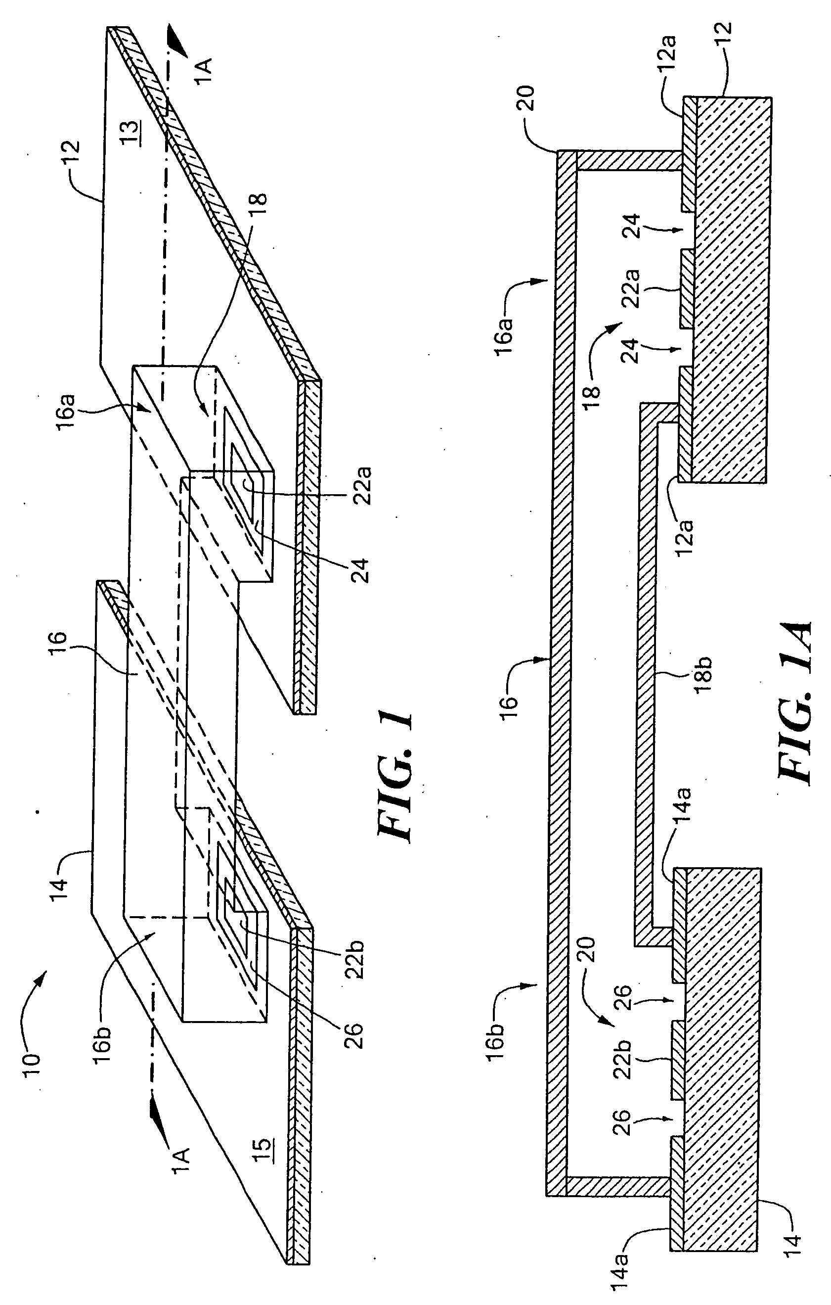
[0032] Referring now to FIGS. 1 and 1A in which like elements are provided having like reference designations, an RF interconnection 10 between first and second radio frequency (RF) Printed Wiring Boards (PWBs) 12, 14 (also sometimes referred to as printed circuit boards or PCBs) includes a waveguide transmission line 16 having first and second ends 16a, 16b (also referred to as waveguide port apertures or more simply waveguide ports) and pair of waveguide feed circuits 18, 20 disposed to launch signals into and couple signals out of the transmission line 16 at ends 16a, 16b, respectively.

[0033] The feed circuits 18, 20 are each provided as an integral part of at least a portion of the PWBs 12, 14 respectively. In the exemplary embodiment shown in FIGS. 1 and 1A, the feed circuits 18, 20 are provided as radiating elements and in particular are provided as micro-strip (or so-called “patch”) antenna elements on PWB surfaces 12a, 14a. Each patch is provided from a conductive region 22...


PUM

PropertyMeasurementUnit
Sizeaaaaaaaaaa
Shapeaaaaaaaaaa
Electrical conductoraaaaaaaaaa

Abstract

A radar electronics module includes a support structure having a first surface having a plurality of recesses with a transmitter circuit board and a receiver circuit board disposed thereon. The transmitter and receiver circuit boards are disposed over the first surface of the supports structure such that transmitter and receive circuits are disposed in cavities on the support structure. The radar electronics module further includes a digital/power supply circuit printed wiring board (PWB) disposed on a second surface of the support structure and a connector disposed on the support structure. The connector is disposed in such a way that it provides electrical connections for at least one of power signals, analog signals or digital signals between at least two of the digital/power supply PWB, the transmitter circuit board and the receiver circuit board.

Description

CROSS-REFERENCE TO RELATED APPLICATIONS [0001] This application claims the benefit of and is a continuation-in-part of co-pending U.S. application Ser. No. 11 / 027,523 filed on Dec. 30, 2004.STATEMENTS REGARDING FEDERALLY SPONSORED RESEARCH [0002] Not applicable. FIELD OF THE INVENTION [0003] This invention relates generally to housings for radio frequency (RF) systems and more particularly to structures and techniques supporting radar structure and circuits. BACKGROUND OF THE INVENTION [0004] As is known in the art, in some applications it is necessary to couple radio frequency (RF) signals between multiple printed wiring boards (PWBs). Such connections are often made by using either a coaxial cable or a printed shielded RF conductor circuit (also referred to as a flex circuit). Both of these techniques are troubled by implementation complexity, reliability concerns, as well as cost issues. [0005] A coaxial cable connection typically requires the mounting of a connecting pin on the ...

Claims


Application Information

Patent Timeline
IPC IPC(8): G01S7/28
CPCG01S7/032H01P5/107H05K1/0237Y10T29/49144G01S13/931H05K9/0007G01S2007/027H05K1/14G01S7/027
Inventor LEBLANC, STEPHEN P.DONOVAN, RICHARD PAULPLEVA, JOSEPH S.
Owner VALEO RADAR SYST
Why Eureka
Try Eureka