
Imaging apparatus and its control method

Inactive Publication Date: 2006-07-13
CANON KK
View PDF1 Cites 9 Cited by
  • Summary
  • Abstract
  • Description
  • Claims
  • Application Information

AI Technical Summary

Benefits of technology

[0006] The present invention has been made in consideration of the aforementioned problems, and has as its object to realize desired color conversion upon imaging by a simple operation by allowing to freely, clearly, and easily set the conversion source color and conversion target color even on a limited user interface of an imaging apparatus.

Problems solved by technology

However, since users have different taste, it is impossible to realize color reproducibility which meets the needs of all users.
However, since it is difficult to present the relationship between changes in parameters and those in colors to the user, optimal settings require user's skill.
However, Japanese Patent Laid-Open No. 2004-129226 pertains to the retouch processing of an image, but it does not set color conversion processing upon imaging in the imaging apparatus.
Also, this method is not suitable for color conversion processing on a limited user interface like that of the imaging apparatus, since that method requires to designate the source color and destination color using the cursor.
However, this method requires an operation unit for cursor movement, and is not suitable for a digital camera or the like which requires portability.
That is, the destination colors are limited to several types, and free color conversion cannot be realized.
Also, since each destination color is not presented to the user as an image, it is difficult for the user to recognize a conversion destination color.

Method used


Image

  • Imaging apparatus and its control method
  • Imaging apparatus and its control method
  • Imaging apparatus and its control method

Examples


first embodiment

k>

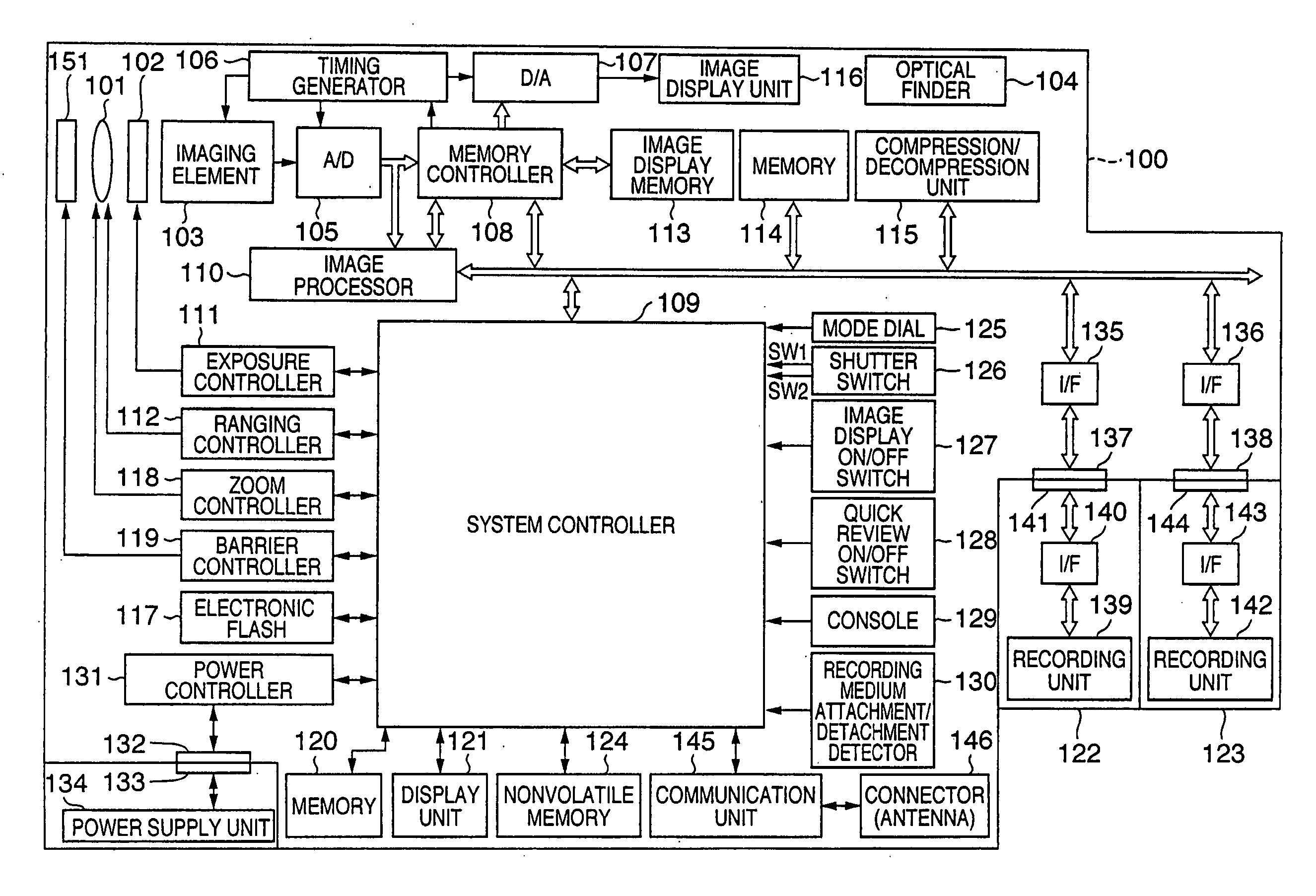
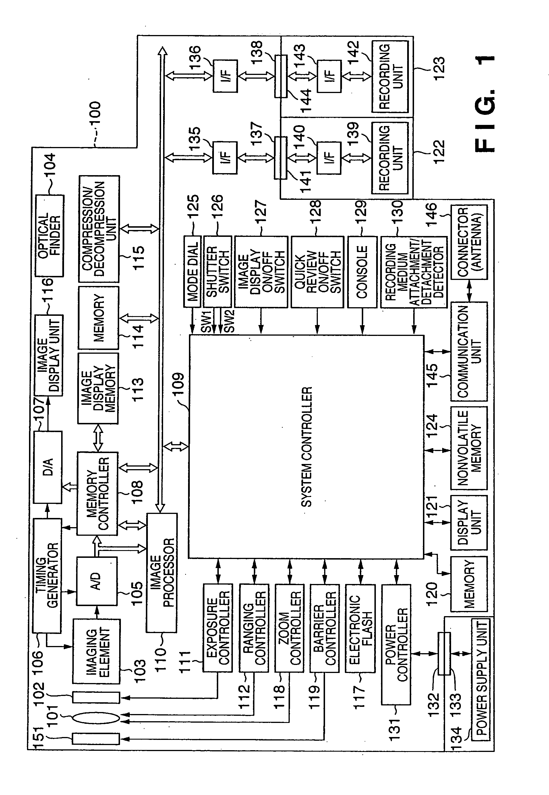
[0024]FIG. 1 is a block diagram showing an example of the arrangement of an imaging apparatus 100 (a digital camera in this example) according to this embodiment. An image on a physical space is formed on an imaging element 103 that converts an optical image into an electrical signal via an imaging lens 101 and a shutter 102 with an aperture function. An A / D converter 105 converts an analog signal output from the imaging element 103 into a digital signal. A timing generator 106 is controlled by a memory controller 108 and system controller 109, and supplies clock signals and control signal to the imaging element 103, the A / D converter 105, and a D / A converter 107.

[0025] An image processor 110 applies predetermined pixel interpolation processing and color conversion processing to data from the A / D converter 105 or the memory controller 108. The image processor 110 executes predetermined arithmetic operation processing using captured image data. The system controller 109 controls a...


PUM


Abstract

In an imaging apparatus which has an imaging unit, an image processor for processing image data obtained by the imaging unit, and recording unit for recording image data output from the image processor, an electronic viewfinder screen is displayed on the basis of image data which is captured by the imaging unit and is output from the image processor, and an image capture frame is also displayed within the screen. A. conversion source color is determined on the basis of color information included in the color capture frame of an image displayed on the electronic viewfinder -screen in response to a first operation input. A conversion destination color is determined on the basis of color information included in the color capture frame of an image displayed on the electronic viewfinder screen in response to a second operation input. Color conversion parameters of the image processor are set so as to convert a color within a predetermined range including the conversion source color into a color within a predetermined range including the conversion destination color on a color space.

Description

FIELD OF THE INVENTION [0001] The present invention relates to an imaging apparatus which allows the user to customize colors, and its control method. BACKGROUND OF THE INVENTION [0002] In recent years, digital cameras have prevailed, and many users increasingly have an opportunity of using digital cameras. For this reason, the users' needs for digital cameras are diversified. As one of such needs, good color reproducibility is known each vendor aims, as a goal of the color reproducibility characteristics, at average color reproduction that most of users feel preferable. However, since users have different taste, it is impossible to realize color reproducibility which meets the needs of all users. [0003] To solve this problem, a digital camera which allows the user to customize parameters such as hue, chroma saturation, brightness, and the like to realize color reproducibility of user's choice upon imaging is available. However, since it is difficult to present the relationship betw...

Claims


Application Information

Patent Timeline
IPC IPC(8): H04N5/222
CPCH04N5/23293H04N9/643H04N9/75H04N23/631H04N23/635H04N23/843H04N25/134H04N9/77
Inventor ASADA, SATOSHI
Owner CANON KK
Learn More