Optical device, image display apparatus, and head-mounted display

a technology of optical devices and display devices, applied in the field of optical devices, image display apparatuses, and head-mounted displays, can solve the problems of poor adhesion between the two materials, difficult fabrication of hologram optical elements, and use of glass as the base material, so as to achieve increased adhesion and higher safety

Inactive Publication Date: 2006-07-13
KONICA MINOLTA PHOTO IMAGING
View PDF5 Cites 36 Cited by
  • Summary
  • Abstract
  • Description
  • Claims
  • Application Information

AI Technical Summary

Benefits of technology

[0011] In view of the conventionally encountered inconveniences discussed above, it is an object of the present invention to provide an optical device that offers increased adhesion between a hologram photosensitive material and a b...

Problems solved by technology

However, while a photopolymer is an organic material, glass used as the base ember is an inorganic material, and this results basically in poor adhesion between the two materials.
This makes a hologram optical element difficult to fabricate.
Moreover, in a case where a hologram optical element so fabricated is used as a combiner in a head-mounted display, the use of glass as t...

Method used


Image

  • Optical device, image display apparatus, and head-mounted display
  • Optical device, image display apparatus, and head-mounted display
  • Optical device, image display apparatus, and head-mounted display

Examples


Embodiment Construction

[0034] Hereinafter, an embodiment of the present invention will be described with reference to the drawings.

1. Head-Mounted Display

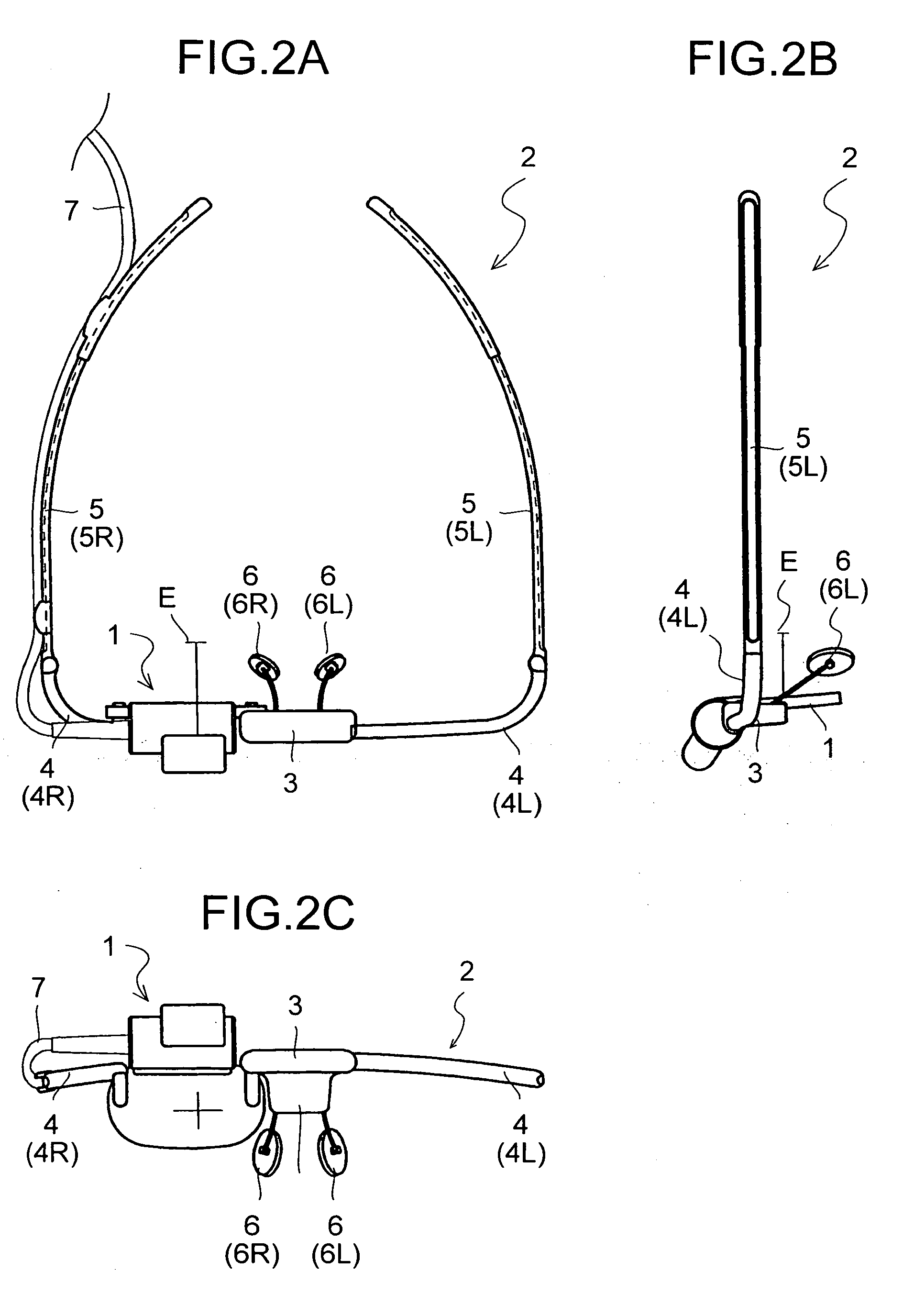
[0035]FIG. 2A is a plan view showing an outline of the structure of a head-mounted display (hereinafter abbreviated to “HMD”) embodying the invention, FIG. 2B is a side view of the same HMD, and FIG. 2C is a front view of the same HMD. The HMD includes an image display apparatus 1 and a supporter 2 that supports it, and has an appearance like that of common eyeglasses of which one of the lenses (for example, the left-eye lens) has been removed.

[0036] The image display apparatus 1 permits an observer to observe the outside-world image in a see-through fashion, and simultaneously displays an image to feed it, as a virtual image, to the observer. In the image display apparatus 1 shown in FIG. 2C, the part thereof that corresponds to the right-eye lens of eyeglasses is composed of two transparent base members 22 and 23 (see FIG. 4), which will be describ...


PUM


Abstract

When an optical device is produced by bonding on a transparent base member an optical element formed as a hologram, the optical element and the transparent base member are both formed of an acrylic material. In particular when, as an optical device, an eyepiece optical system is produced by holding an optical element between two transparent base members, the optical element, the transparent base members, and the adhesive with which the transparent base members are joined together are all formed of an acrylic material. In this way, by building an eyepiece optical system with a similar kind of material, namely an acrylic material, it is possible to obtain increased adhesion among the materials of the individual components of the eyepiece optical system without performing special processing. Moreover, the transparent base members formed of an acrylic material more securely absorb shock and external pressure than those formed of glass.

Description

[0001] This application is based on Japanese Patent Application No. 2004-351706 filed on Dec. 3, 2004, the contents of which are hereby incorporated by reference. BACKGROUND OF THE INVENTION [0002] 1. Field of the Invention [0003] The present invention relates to an optical device having a hologram optical element bonded on a transparent base member, relates also to an image display apparatus employing such an optical device, and relates further to a head-mounted display employing such an image display apparatus. [0004] 2. Description of Related Art [0005] An optical element such as a hologram, a half-mirror coat, or a beam splitter layer, when used embedded in a transparent base member (held between two transparent base members), is not affected by ambient factors such as humidity and oxygen. Thus, such an optical element is very useful as a combiner in, for example, a head-up display or a head-mounted display. [0006] In general, a head-up display, a hologram screen, or the like is...

Claims


Application Information

Patent Timeline
IPC IPC(8): G03H1/00
CPCG02B27/0103G03H1/0272G03H2270/55
Inventor NODA, TETSUYATANIJIRI, YASUSHIKASAI, ICHIRO
Owner KONICA MINOLTA PHOTO IMAGING
Why Eureka
Try Eureka