Hologram recording method, hologram recording apparatus, and hologram recording medium

Inactive Publication Date: 2006-07-13
FUJIFILM HLDG CORP
View PDF2 Cites 22 Cited by
  • Summary
  • Abstract
  • Description
  • Claims
  • Application Information

AI Technical Summary

Benefits of technology

[0015] It is therefore an object of the present invention to provide a hologram recording method which enables obtaining floating and high-quality images which can be stereoscopically viewed fr

Problems solved by technology

When white light such as sunlight is irradiated to a hologram, the reproduced stereoscopic image blurs and cannot be clearly reproduced, because lights at various wavelengths are mixed.
However, in the case of the recording method, the object beam is irradiated to the static object from one direction, therefore, the range where the image is viewable as a stereoscopic image to be recorded is limited, and it is impossible to obtain a circumferentially-viewed stereoscopic image, and it leaves much to be desired as a stereoscopic image.
However, when using the hologram recording method, there is a problem that it is impossible to reproduce a stereoscopic image of the object viewed from the elevated directions of the object, which ar

Method used


Image

  • Hologram recording method, hologram recording apparatus, and hologram recording medium
  • Hologram recording method, hologram recording apparatus, and hologram recording medium
  • Hologram recording method, hologram recording apparatus, and hologram recording medium

Examples


example 1

—Production of Hologram Recording Apparatus—

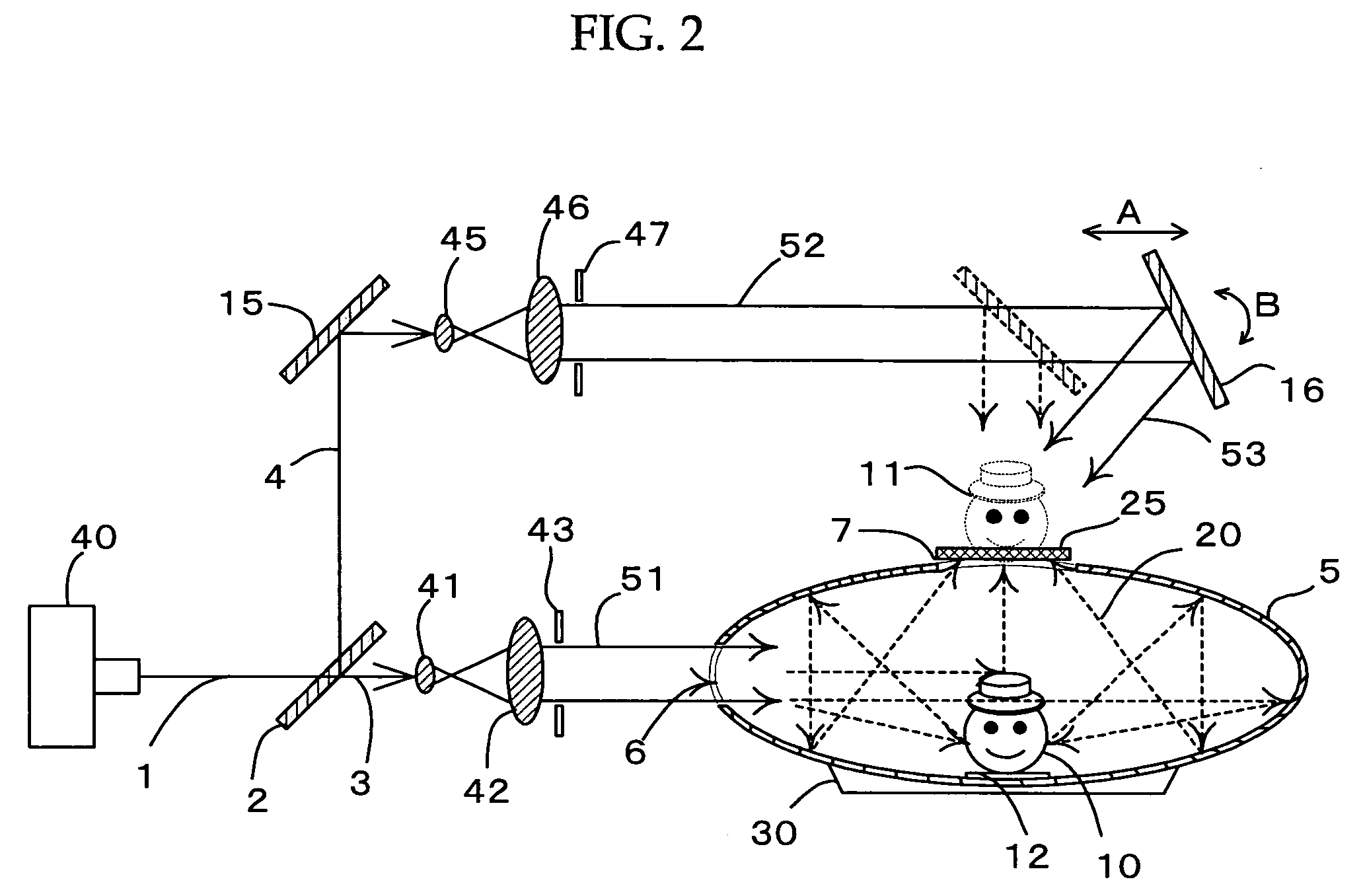
[0119] The hologram recording apparatus produced in Example 1 is schematically shown in FIG. 2.

—Object Beam System and Reference Beam System—

[0120] Laser oscillator 40 is a He—Ne semiconductor laser oscillator having a rating of 10 mW. The laser oscillator was used as a light source for the object beam system and the reference beam system. The oscillation wavelength of the laser beam was set at 632.8 nm. A plate type non-polarized half mirror was used for half mirror 2 in which the ratio of the amount of reflected beams to the amount of transmitted beams was split at a ratio of 1:1.

[0121] Galileo beam expanders each using two sheets of ZnSe lenses were used for beam expanders 41 and 42, and 45 and 46.

[0122] For apertures 43, and 47, aperture plates HOM-4.0 (having an aperture diameter of 4 mm, a circular form, manufactured by OFR Inc.) were used.

[0123] For mirror 15, a plane mirror with no concave convex formed thereon was used, and a ...


PUM


Abstract

The present invention provides a hologram recording method which enables obtaining floating and high-quality images which can be stereoscopically viewed from wide viewing angles of 360° in a low-cost and simple production method and to provide a hologram recording apparatus and a hologram recording medium. Thus, the present invention relates to a hologram recording method which includes irradiating a coherent object beam virtually simultaneously to almost all the surface of a recording object to make the reflected object beam from the surface incident on a photosensitive surface of a photosensitive material, making a coherent reference beam incident on the opposite surface of the photosensitive material with respect to the photosensitive surface to generate interference fringes by the object beam and the reference beam, and recording the interference fringes on the photosensitive material, and a hologram recording medium and a hologram recording apparatus using the method.

Description

BACKGROUND OF THE INVENTION [0001] 1. Field of the Invention [0002] The present invention relates to an image recording method, particularly relates to a hologram recording method which enables obtaining floating and high-quality images which can be stereoscopically viewed from wide viewing angles of 360° in a low-cost and simple production method. The present invention also relates to a hologram recording apparatus and a hologram recording medium using the hologram recording method. [0003] 2. Description of the Related Art [0004] A hologram recorded by means of holography is a one in which interference fringes caused by coherence between object beams reflected from an object and a reference beam which is irradiated separately from the object beam are recorded, and when a beam same as the reference beam is irradiated to the hologram, a stereoscopic image same as the original object can be viewed. [0005] To generate the interference fringes, a beam which is coherent, has visuospatial...

Claims


Application Information

Patent Timeline
IPC IPC(8): G03H1/02
CPCG02B27/2292G03H1/0406G03H2001/026G03H2001/0415G03H2001/0426G03H2001/226G03H2001/2263G03H2223/24G02B30/56
Inventor USAMI, YOSHIHISA
Owner FUJIFILM HLDG CORP
Why Eureka
Try Eureka