
DC/DC converter with current limit protection

Active Publication Date: 2006-07-13
ANALOG DEVICES INT UNLTD
View PDF8 Cites 15 Cited by
  • Summary
  • Abstract
  • Description
  • Claims
  • Application Information

AI Technical Summary

Benefits of technology

[0009] In operation, the first circuit point is coupled by the switch to the second circuit point in response to the load parameter, for example load voltage, exceeding a predetermined level. The first circuit point is decoupled from the second circuit point in response to a current therebetween exceeding a current threshold level during the coupled state. Recoupling of the first circuit point to the second circuit point is delayed thereafter by at least a fixed timed period. During an excessive current condition at the second circuit point, recoupling is inhibited. The off-time of the switch thus is adjusted as much as needed to achieve a target inductor current before the switch is turned on. An oscillator period or fixed off-time thus can then be set to smaller values than in conventional regulators, thus realizing smaller external component sizes and higher power densities.

Problems solved by technology

These methods sense a low output feedback condition and accordingly increase an oscillator period in the control circuit of the switch, or increase the delay period, to lengthen the switch off-time by a fixed amount.
Frequency foldback methods are disadvantageous in that the increased off-time may not be sufficient to prevent switch current runaway.
Because of the uncertainty about external element values, the set off-time may be made too long, thereby unnecessarily (VIN) constraining output current capability during normal operation.

Method used


Image

  • DC/DC converter with current limit protection
  • DC/DC converter with current limit protection
  • DC/DC converter with current limit protection

Examples


Embodiment Construction

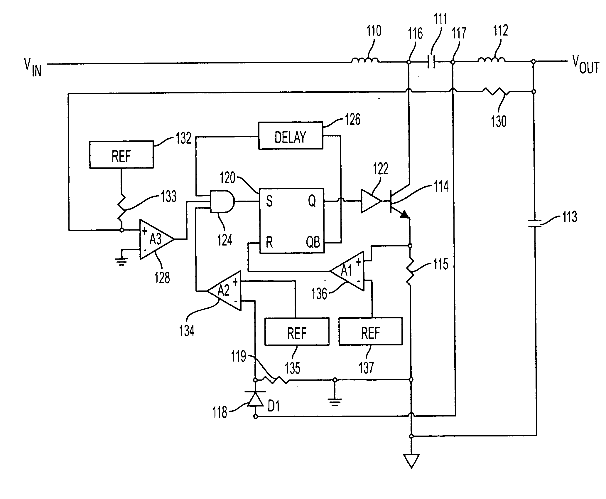
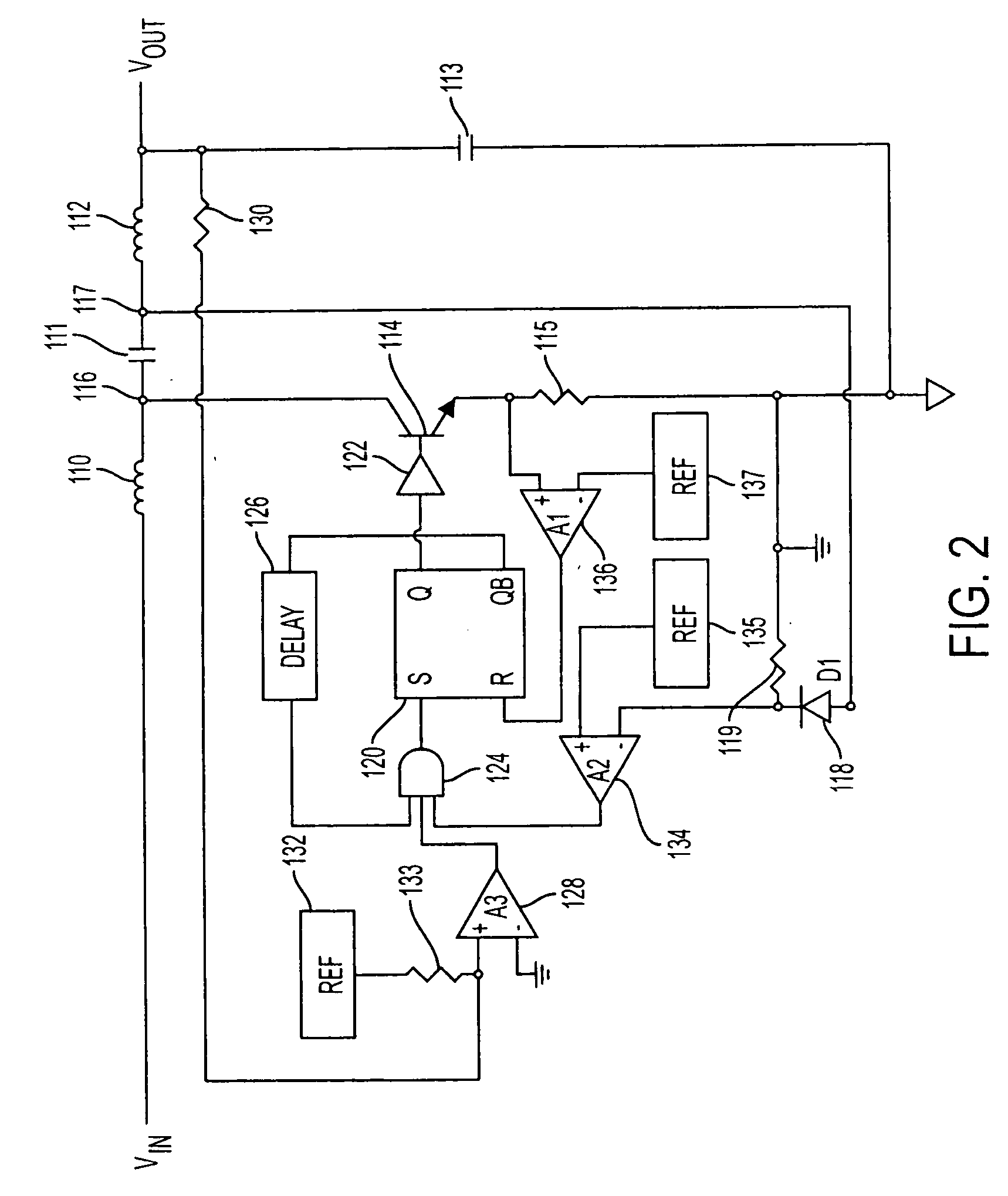
[0014] The invention is exemplified by the diagram of FIG. 2, which illustrates an inverting DC / DC converter having a positive input voltage VIN, for example five volts, and a negative output voltage VOUT, for example negative eight volts. It should be understood that the invention is applicable to other boost converter circuits that can provide a regulated output voltage, at either polarity, of any particular desired level from any given DC source. Connected in series between input terminal VIN and output terminal VOUT are inductor 110, capacitor 111, and inductor 112. Capacitor 113 is connected between the output terminal and ground. Signal responsive switch 114, shown as a transistor, and resistor 115 are connected in series between the circuit point 116, which joins inductor 110 and capacitor 111, and ground. Capacitor 111 is connected to inductor 112 at circuit point 117. Connected in series between circuit point 117 and ground are schottky diode 118 and resistor 119. The base ...


PUM


Abstract

A converter coupled to a DC voltage input and connectable to a load, includes a signal responsive switch coupled between a first circuit point and a second circuit point. Current flow is directed by the switch, when in a closed state, to the second circuit point to bypass the load. A regulator circuit has an output coupled to a control input of the switch. The regulator circuit has a first input for receiving a sensed load parameter, a second input for receiving a sensed current level signal at the second circuit point when the switch is in its closed state, and a third input for receiving a sensed current level signal at the second circuit point, measured directly, when the switch is in an open state. A fixed minimum time is set for the switch to be in the open state. The third input inhibits re-closing of the switch, providing current limit protection for the switch.

Description

FIELD OF THE INVENTION [0001] The present invention relates to direct current voltage regulators, more particularly to controlled limitation of current in DC / DC converters. BACKGROUND [0002] A conventional step-up DC / DC converter is illustrated in FIG. 1. Inductor 10 and diode 12 are connected in series between input (VIN) and output (VOUT) terminals. The input terminal is typically connected to a DC source, the controlled output connected to a load. Capacitor 14 is connected between the output terminal and ground. Signal responsive switch 16 and resistor 18 are connected in series between the inductor / diode junction and ground. The switch is represented by a transistor having a base connected to the output of latch 20 through switch driver circuit 22. A set terminal of the latch is connected to the output of AND gate 24. Delay circuit 26 has an input connected to the reset output of the latch and an output connected to a first input of the AND gate. A second input of the AND gate i...

Claims


Application Information

Patent Timeline
IPC IPC(8): H02H3/08
CPCH02M1/32H02M3/005H02M3/156H02M2001/0009A61H3/066E01C5/22E01C15/00
Inventor YOUNG, ERIC
Owner ANALOG DEVICES INT UNLTD
Features
  • Generate Ideas
  • Intellectual Property
  • Life Sciences
  • Materials
  • Tech Scout
  • Unparalleled Data Quality
  • Higher Quality Content
  • 60% Fewer Hallucinations
Learn More