Multilayer capacitor and method of adjusting equivalent series resistance of multilayer capacitor

a multi-layer capacitor and equivalent series resistance technology, applied in the direction of fixed capacitor details, feed-through capacitors, instruments, etc., can solve the problem of difficult and achieve the effect of easy regulation of equivalent series resistance and high precision

Active Publication Date: 2006-07-13
TDK CORPARATION
View PDF8 Cites 24 Cited by
  • Summary
  • Abstract
  • Description
  • Claims
  • Application Information

AI Technical Summary

Benefits of technology

[0027] The present invention can provide a multilayer capacitor and a method of adjusting an equivalent series resi

Problems solved by technology

However, the following problem exists in the multilayer capacitor disclosed in Japanese Patent Application Laid-Open No. 2004-47983 when adjusting the equivalent series resistance to a desirable value.
Namely, for adjusting the equivalent series resistance to a desirable value, the multilayer capaci

Method used


Image

  • Multilayer capacitor and method of adjusting equivalent series resistance of multilayer capacitor
  • Multilayer capacitor and method of adjusting equivalent series resistance of multilayer capacitor
  • Multilayer capacitor and method of adjusting equivalent series resistance of multilayer capacitor

Examples


first embodiment

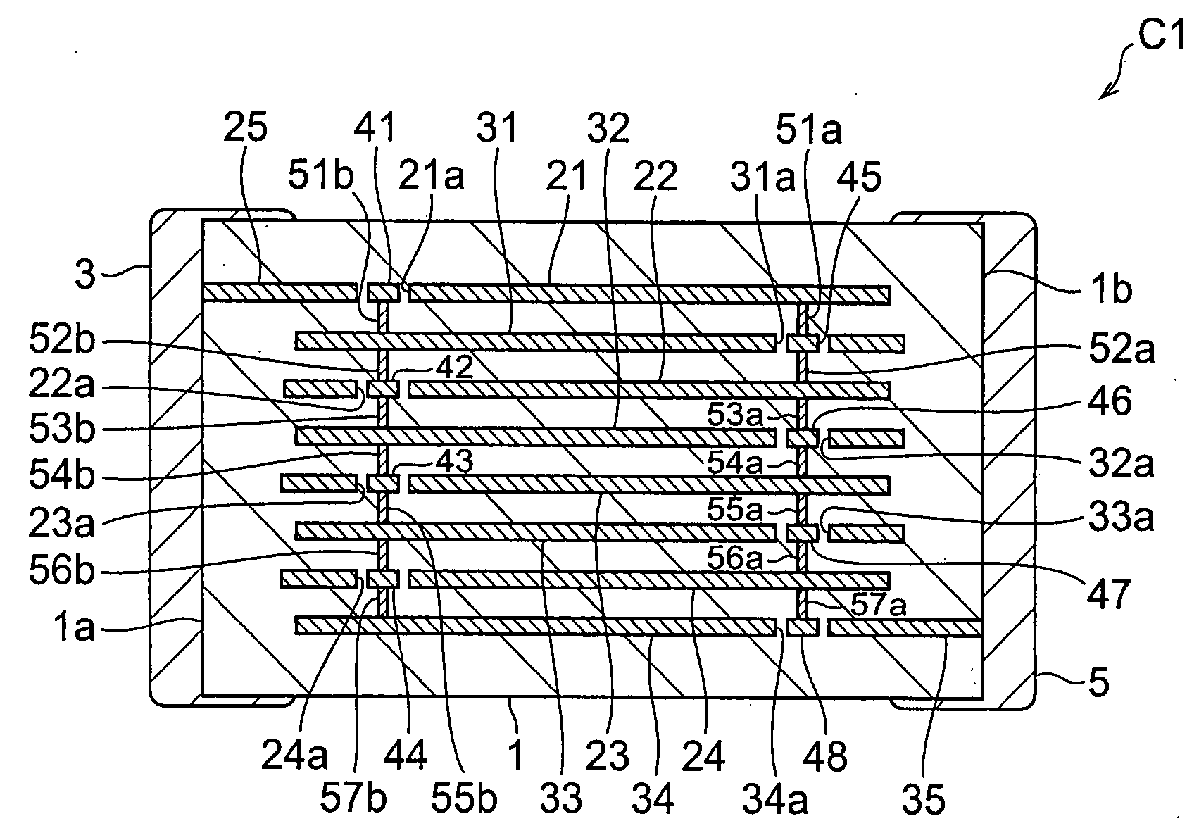
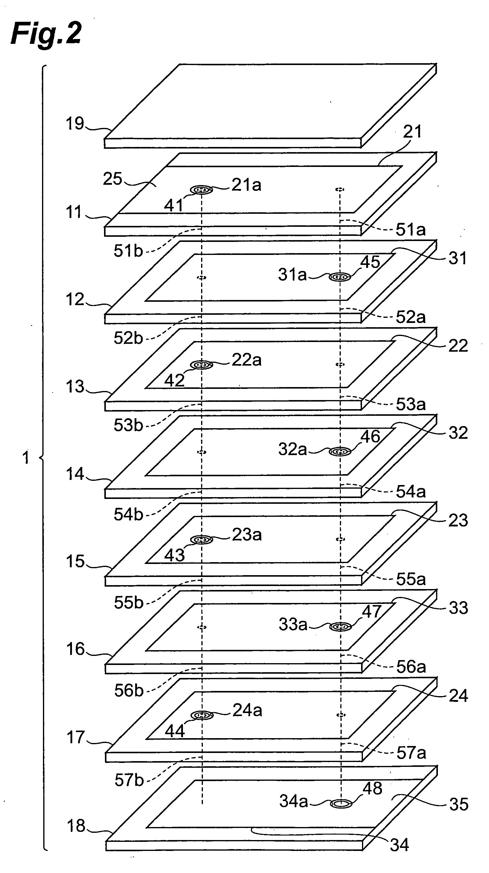
[0058] With reference to FIGS. 1 and 2, the structure of the multilayer capacitor C1 in accordance with a first embodiment will be explained. FIG. 1 is a view for explaining a cross-sectional configuration of the multilayer capacitor in accordance with the first embodiment. FIG. 2 is an exploded perspective view of the multilayer body included in the multilayer capacitor in accordance with the first embodiment.

[0059] As shown in FIG. 1, the multilayer capacitor C1 comprises a multilayer body 1 and first and second terminal electrodes 3, 5 which are formed on the multilayer body 1.

[0060] The first terminal electrode 3 is positioned on the side of a side face 1a of the multilayer body 1. The second electrode 5 is positioned on the side of a side face 1b of the multilayer body 1. The first terminal electrode 3 and the second terminal electrode 5 are electrically insulated from each other.

[0061] As also shown in FIG. 2, the multilayer body 1 is constructed by alternately laminating a...

second embodiment

[0078] The structure of the multilayer capacitor C2 in accordance with a second embodiment will be explained with reference to FIGS. 3 and 4. The multilayer capacitor C2 in accordance with the second embodiment differs from the multilayer capacitor C1 in accordance with the first embodiment in terms of the position of the second inner electrode 31 connected to the second terminal electrode 5 by way of the lead conductor 35 in the laminating direction. FIG. 3 is a view for explaining a cross-sectional configuration of the multilayer capacitor in accordance with the second embodiment. FIG. 4 is an exploded perspective view of the multilayer body included in the multilayer capacitor in accordance with the second embodiment.

[0079] Among the four second inner electrodes 31 to 34 in the multilayer capacitor C2, the uppermost one 31 is electrically connected to the second terminal electrode 5 by way of the lead conductor 35 as shown in FIGS. 3 and 4. This electrically connects the second ...

third embodiment

[0083] With reference to FIGS. 5 and 6, the structure of the multilayer capacitor C3 in accordance with a third embodiment will be explained. The multilayer capacitor C3 in accordance with the third embodiment differs from the multilayer capacitor C1 in accordance with the first embodiment in terms of positions of the first and second inner electrodes 23, 32 connected to the terminal electrodes 3, 5 by way of the lead conductors 25, 35 in the laminating direction. FIG. 5 is a view for explaining a cross-sectional configuration of the multilayer capacitor in accordance with the third embodiment. FIG. 6 is an exploded perspective view of the multilayer body included in the multilayer capacitor in accordance with the third embodiment.

[0084] Among the four first inner electrodes 21 to 24 in the multilayer capacitor C3, the third one 23 counted downward from the first inner electrode 21 is electrically connected to the first terminal electrode 3 by way of the lead conductor 25 as shown ...


PUM

PropertyMeasurementUnit
Timeaaaaaaaaaa
Electrical resistanceaaaaaaaaaa

Abstract

A multilayer capacitor comprises a multilayer body in which a plurality of dielectric layers and a plurality of inner electrodes are alternately laminated, and a plurality of terminal electrodes formed on the multilayer body. The plurality of inner electrodes include a plurality of first inner electrodes and a plurality of second inner electrodes alternately arranged. The plurality of terminal electrodes include first and second terminal electrodes electrically insulated from each other. The plurality of first inner electrodes are electrically connected to each other by way of a through-hole conductor. The plurality of second inner electrodes are electrically connected to each other by way of a through-hole conductor. In the plurality of first inner electrodes, at least one first inner electrode whose number is smaller than the total number of first inner electrodes by at least 1 is electrically connected to the first terminal electrode by way of a lead conductor. In the plurality of second inner electrodes, at least one second inner electrode whose number is smaller than the total number of second inner electrodes by at least 1 is electrically connected to the second terminal electrode by way of a lead conductor. An equivalent series resistance is set to a desirable value by adjusting each of the number of first inner electrodes electrically connected to the first terminal electrode by way of the lead conductor and the number of second inner electrodes electrically connected to the second terminal electrode by way of the lead conductor.

Description

BACKGROUND OF THE INVENTION [0001] 1. Field of the Invention [0002] The present invention relates to a multilayer capacitor and a method of adjusting an equivalent series resistance of a multilayer capacitor. [0003] 2. Related Background Art [0004] Known as this kind of multilayer capacitor is one comprising a multilayer body in which a plurality of dielectric layers and a plurality of inner electrodes are alternately laminated, and a plurality of terminal electrodes formed on the multilayer body (see, for example, Japanese Patent Application Laid-Open No. 2004-47983). [0005] Power supplies for central processing units (CPUs) mounted in digital electronic devices have been increasing their load current while lowering their voltage. Therefore, it has become quite difficult to suppress the fluctuation in power supply voltage under a tolerable level in response to a drastic change in load current, whereby a multilayer capacitor known as decoupling capacitor has come into use so as to b...

Claims


Application Information

Patent Timeline
IPC IPC(8): H01G4/228
CPCH01G4/012H01G4/232Y10T29/435H01G4/35H01G4/30G06F1/26G06F13/4081
Inventor TOGASHI, MASAAKIAHIKO, TAISUKE
Owner TDK CORPARATION
Why Eureka
Try Eureka