Current controlled switch mode power supply

a current control and power supply technology, applied in the direction of electric variable regulation, process and machine control, instruments, etc., can solve the problems of reducing longevity, increasing cost, and experiencing higher stress on the switching device, so as to reduce the stress on the device operating, reduce heat loss, and optimize the power factor

Active Publication Date: 2006-07-13
HARMAN INT IND INC
View PDF3 Cites 105 Cited by
  • Summary
  • Abstract
  • Description
  • Claims
  • Application Information

AI Technical Summary

Benefits of technology

[0007] The present invention includes a power converter (or power supply) that is a single stage power converter configured to combine power factor correction and galvanic isolation in a single stage. The power converter includes sets of switches that may be controlled to maintain a substantially constant line current from a power line, such as an AC line, supplying the power converter. In addition, the power converter may optimize the power factor of the power converter. Instead of focusing on achievement of a unity power factor, the power converter may beneficially operate to control the shape of the current imposed on the power supply line. This may allow the capability to achieve nearly unity power factor as well as reduce device stress in devices operating in the power converter. As a result, less heat may be produced and the number of parallel devices employed in the power converter may be reduced.

Problems solved by technology

In addition, higher stresses on the switching devices may be experienced during operation.
These factors tend to increase cost, reduce longevity and reduce overall efficiency of the power converter.
Overall efficiency can be compromised by energy loss and accompanying buildup of heat that accompanies such high magnitude current and voltage switching.

Method used


Image

  • Current controlled switch mode power supply
  • Current controlled switch mode power supply
  • Current controlled switch mode power supply

Examples


Embodiment Construction

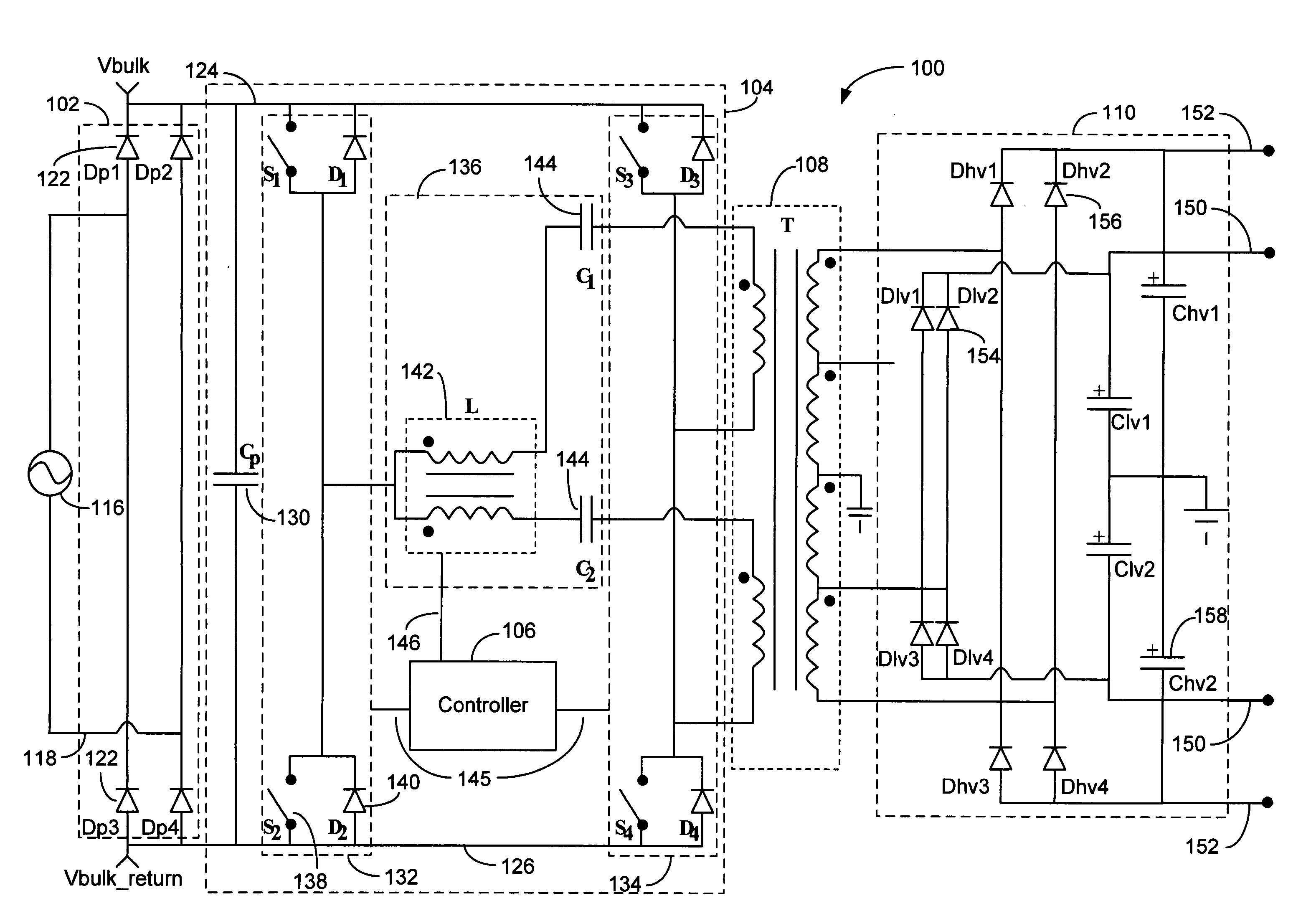
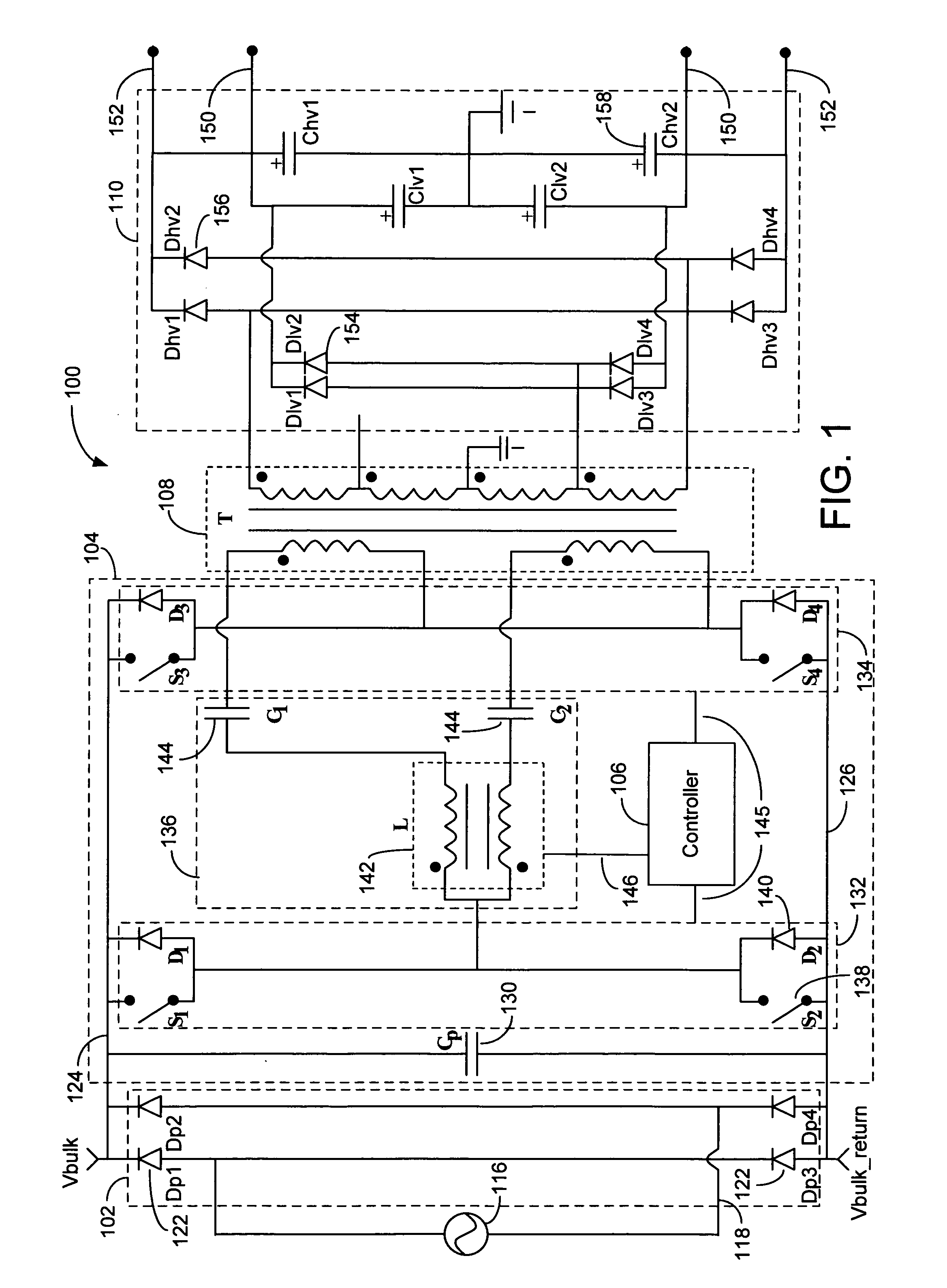
[0022]FIG. 1 is a simplified circuit schematic of an example power processing stage of a power converter 100. The power converter 100 includes an input rectifier 102, a switching stage 104, a controller 106, a transformer 108, and an output rectifier 110 that includes associated storage capacitance. In other examples, other configurations of power processing stages that are capable of providing switched mode power conversion are possible.

[0023] In FIG. 1, power processing begins with a supply line input voltage and a supply line input current provided by a power source 116, such as an AC power source provided by an electricity supply company, on a supply line 118. In some examples, the AC power source may include electromagnetic interference (EMI) filtering capabilities, such as with an EMI line filter. The line input voltage may be full-bridge rectified by the input rectifier 102. The input rectifier 102 may be any system or device capable of rectifying an AC voltage. The example ...


PUM


Abstract

A single stage switch mode power converter receives a supply line voltage and a supply line current from a power supply line, and provides one or more regulated output voltages for a load, such as an amplifier. The power converter is operable to regulate the output voltage(s) using a controller that includes a voltage controlled current loop. The controller can enable substantially constant supply line current to be drawn from the power supply line by selectively allowing conduction of the supply line current through the power converter. A power factor of the supply line voltage and the supply line current may be optimized by the controller at medium to high power levels thereby maximizing the power provided to the switch mode power converter from the power supply line. Due to the adaptive nature of the controller, the power converter can operate over a wide range of supply line voltage.

Description

PRIORITY CLAIM [0001] This application claims the benefit of priority from U.S. Provisional Application No. 60 / 642,214, filed Jan. 7, 2005, which is incorporated by reference.BACKGROUND OF THE INVENTION [0002] 1. Technical Field [0003] The invention generally relates to switch mode power supplies. More particularly, the invention relates to switch mode power supplies that are current controlled to maintain a substantially constant line current at an optimized power factor. [0004] 2. Related Art [0005] As the power capability of a power converter, or power supply, grows, the need to better utilize the power source follows close behind. The distribution of power throughout the world has coalesced on a sinusoidal AC network leading to the advent of power factor corrected processing. Prior developed power factor correction or PFC stages have used a two-stage boost based converter, or a single stage converter to achieve the voltage requirements for a load on the power supply and to achie...

Claims


Application Information

Patent Timeline
Patent Type & Authority Applications(United States)
IPC IPC(8): H02M3/335H02M1/00H02M1/42
CPCH02M1/4241H02M1/425H02M3/33507H02M2001/009Y02B70/126Y02B70/1433H02M7/5387Y02B70/10H02M1/009H02M7/4815
Inventor BAKER, ERIC MATTHEWBUSQUETS-MONGE, SERGIOSTANLEY, GERALD R.
Owner HARMAN INT IND INC
Why Eureka
Try Eureka