Furling wind turbine

a wind turbine and wind power technology, applied in the field of furling wind turbines, can solve the problem that the centrifugal brake must be much larger

Inactive Publication Date: 2006-07-13
DAVIS DEAN A
View PDF8 Cites 25 Cited by
  • Summary
  • Abstract
  • Description
  • Claims
  • Application Information

AI Technical Summary

Benefits of technology

[0011] As additional protection against rotor over-speed conditions, the wind turbine is equipped with an electrically released mechanical brake and a back-up centrifugal brake, which may be either coupled directly to the rotor shaft or to the gearbox output shaft. The centrifugal brake will function in the event of the mechanical brake's failure. The former arrangement has the advantage that

Problems solved by technology

A fault condition may occur when the electrical power grid, to which the wind turbine is connected, fails, when the alternator armature winding develops an open circuit and causes an unloading of the turbine, or when the gearbox break

Method used


Image

  • Furling wind turbine
  • Furling wind turbine
  • Furling wind turbine

Examples


Embodiment Construction

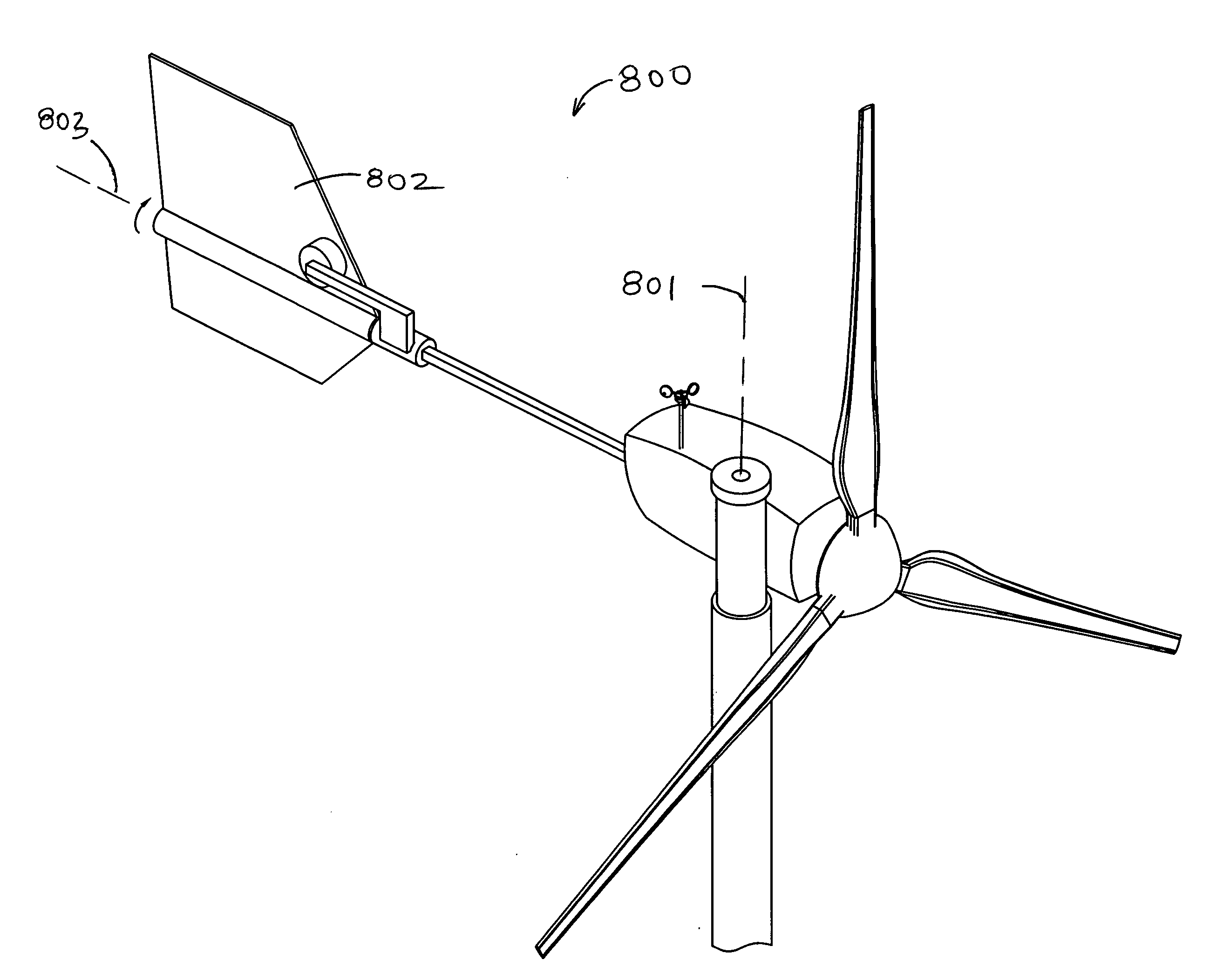
[0022] A latching mechanism is employed in a furling wind turbine to keep the tail from furling during normal operation, but allowing the tail to release as a means of rotor aerodynamic braking. The latch may be actively or passively controlled. Using active control sensing, the rotor speed is sensed either directly or indirectly by, for example, measuring the current generated. If the sensed value exceeds a set value, the latch is disengaged, allowing the tail to furl and moving the rotor oblique to the direction of the wind. Using passive control, the latch disengages under the action of rotor aerodynamic forces or moments.

[0023] For active furling control, the tail may be latched with an electromagnet. When rotor speed reaches a set value that equates a safe operational limit, the electromagnet is released. In addition, a fault condition will automatically release the electromagnet. Active furling control may also be implemented using a stepper motor to optimize the furling angl...


PUM


Abstract

A stall control wind turbine is eguipped with a latchable furling mechanism so that, except in the event of a fault condition or dangerously high winds, the rotor faces directly into the prevailing wind while generating power. A fault condition may occur when the electrical power grid, to which the wind turbine is connected, fails, when the alternator armature winding develops an open circuit and causes an unloading of the turbine, or when the gearbox breaks, also causing an unloading of the turbine. For a preferred embodiment of the invention, the release mechanism employs an electromagnet, which when energized, maintains the tail boom locked in place and the tail in the proper position to maintain the aerodynamic force. The wind turbine may also be eguipped with an electrically released mechanical brake and a back-up centrifugal brake.

Description

[0001] This application has a priority date based on Provisional Patent Application No. 60 / 465,349, which was filed on Apr. 24, 2003.BACKGROUND OF THE INVENTION [0002] 1. Field of the Invention [0003] This invention generally relates to furling wind turbines and, more particularly, to a wind turbine having latched furling. [0004] 2. Description of the Prior Art [0005] Many small prior-art variable-speed wind turbines have a pivoting, or furling, tail to reduce the power output and structural loading during periods of high wind speed. FIGS. 1, 2 and 3 illustrate such a feature. For each of these figures, the turbine blades 101 are coupled to a generator or alternator 102 via a turbine shaft 103. The generator housing 104 is coupled to a tower (not shown) via a vertically-oriented pivot 105 that is laterally offset from the turbine axis 106. The tail vane 107 is hingeably mounted to the generator housing 104. It is spring or gravity-biased toward a position where it is inline with the...

Claims


Application Information

Patent Timeline
IPC IPC(8): F03D7/06
CPCF03D7/0208F03D7/0212F03D7/0248F03D7/0268Y02E10/723Y02E10/72
Inventor DAVIS, DEAN A.
Owner DAVIS DEAN A
Why Eureka
Try Eureka