Flexible stent and method of making the same

a flexible, intralumenal technology, applied in the field of expandable intralumenal prostheses, can solve problems such as stroke and severe trauma

Inactive Publication Date: 2006-07-13
TC1 LLC
View PDF80 Cites 40 Cited by
  • Summary
  • Abstract
  • Description
  • Claims
  • Application Information

AI Technical Summary

Benefits of technology

[0014] In accordance with another aspect of the embodiments of the present invention, a method for manufacturing a stent is provided. The method of manufacturing can include forming a band made at least in-part from polymer on a mandrel, positioning an end of a first member on a first end of the band, positioning an end of a second member on a second end of the band, and increasing the thickness of the band to encapsulate the ends of the first and second members. This method of manufacturing can flexibly connect the first member to the second member.

Problems solved by technology

The thrombi can form emboli that occlude vessels, leading to severe trauma such as strokes.

Method used


Image

  • Flexible stent and method of making the same
  • Flexible stent and method of making the same
  • Flexible stent and method of making the same

Examples


Embodiment Construction

Apparatus

Embodiment With Polymer Layer

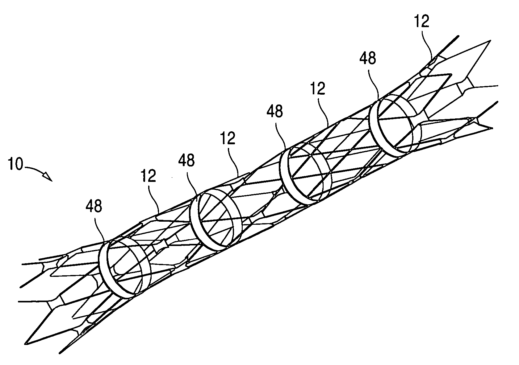
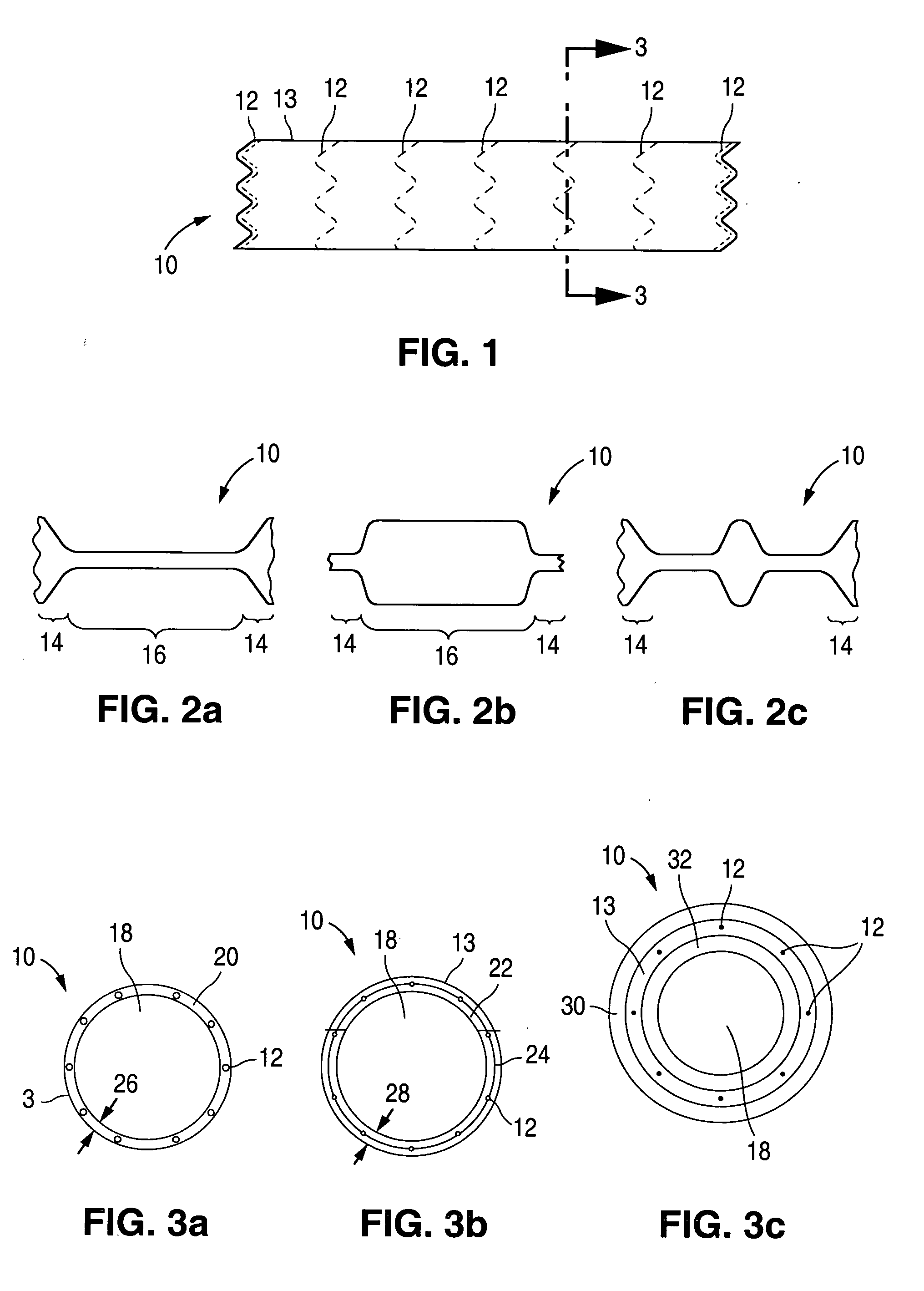
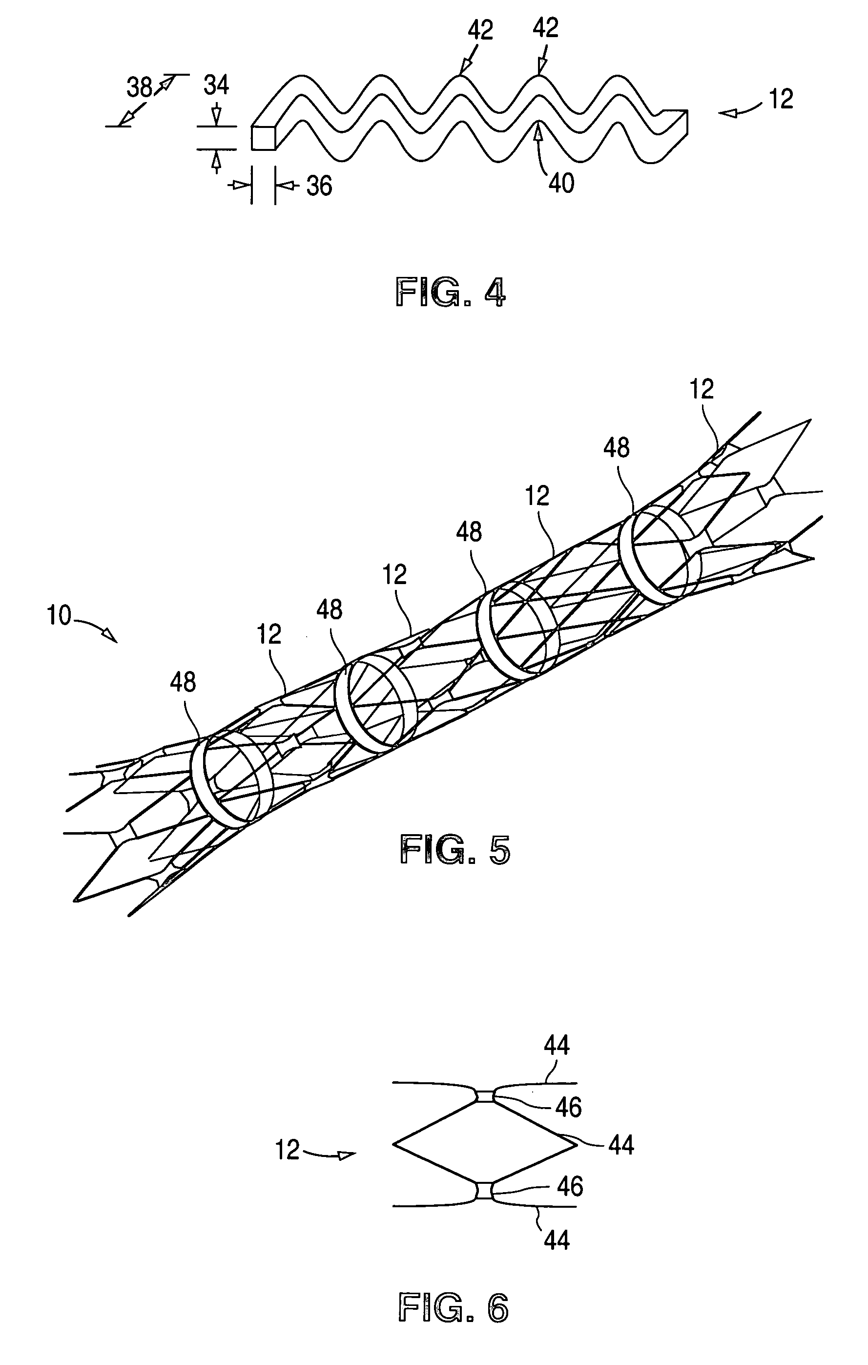
[0026]FIG. 1 illustrates an embodiment of a stent 10 that can have individual, disconnected structural rings 12 flexibly connected to one another by a polymer layer 13. The structural rings 12 can be a combination of balloon expandable structural rings 12 and self-expandable structural rings 12 or can all be the same type of structural ring 12 (i.e., all balloon expandable or all self-expandable). The stent 10 can have a length of about 0.5 cm (0.2 in.) to about 30 cm (10 in.), for example about 3 cm (1 in.).

[0027]FIGS. 2a-2c show three separate embodiments of the stent 10 with the self-expandable structural rings 12 expanded and the balloon expandable structural rings 12 collapsed. The embodiment illustrated in FIG. 2a can have self-expandable structural rings 12 at end sections 14 and balloon expandable structural rings 12 in a middle section 16. During deployment, this embodiment can create an isolated space between the stent 10 and the ...


PUM


Abstract

A stent that can be made of self-expandable members and balloon expandable members is described. The members can be held together by a polymer layer, polymer rings or discreet polymer connectors. Methods of making and using the stent are also described.

Description

CROSS REFERENCE [0001] This application is a divisional application of Ser. No. 10 / 108,778 filed on Mar. 26, 2002.TECHNICAL FIELD [0002] This invention relates to expandable intralumenal prostheses, commonly known as stents. BACKGROUND OF THE INVENTION [0003] Stents are used to treat occlusions in body vessels. Stents can be grouped based on their method of deployment: balloon expandable or self-expandable. Normally a balloon expandable stent is radially compressed onto a non-compliant balloon. The balloon expandable stent has a high radial strength, but when compressed it remains in the compressed state. When the balloon is inflated, the stent radially expands and maintains its shape after the deflation of the balloon. Balloon expandable stents are advantageous because they can be easily deformed for use in locations of curvature or where side branch access is required. Balloon expandable stents can also produce a higher radial force than self-expandable stents during deployment du...

Claims


Application Information

Patent Timeline
Patent Type & Authority Applications(United States)
IPC IPC(8): A61F2/90A61F2/00A61F2/82A61F2/86
CPCA61F2/07A61F2/86A61F2002/828A61F2250/0048A61F2230/0054A61F2210/0076A61F2220/0033A61F2220/005A61F2220/0058A61F2230/0078A61F2230/008
Inventor HOLLOWAY, KEN A.CHRISTOFOROU, CHRISTOFER T.
Owner TC1 LLC
Why Eureka
Try Eureka