Data generation and transmission system in agricultural working machines

a technology for agricultural working machines and transmission systems, applied in the field of data generation and transmission systems in agricultural working machines, can solve the problems of long transmission paths that require high transmission efficiency, complex data exchange systems, and inability to easily transmit long transmission paths,

Active Publication Date: 2006-07-13
CLAAS SELBSTFAHRENDE ERNTEMASCHINEN GMBH
View PDF6 Cites 27 Cited by
  • Summary
  • Abstract
  • Description
  • Claims
  • Application Information

AI Technical Summary

Benefits of technology

[0003] It is therefore the object of the present invention to provide a data generation and transmission system in agricultural working machines that prevents the disadvantages of

Problems solved by technology

Embodiments of this type have the disadvantage, in particular, that a large number of smaller battery units must be assigned directly to the particular sensor elements, resulting in data exchange systems that are complex in design and expensive.
On the other hand, the assignment of a centralized energy source has the disadvantage that long transmission paths require high transmission efficiencies that often cannot be easily transmitted across the distances to be covered in an agricultural working machine.
This type of data transmission has various disadvantages, however, due to the fact that it must be connected

Method used


Image

  • Data generation and transmission system in agricultural working machines
  • Data generation and transmission system in agricultural working machines
  • Data generation and transmission system in agricultural working machines

Examples


first embodiment

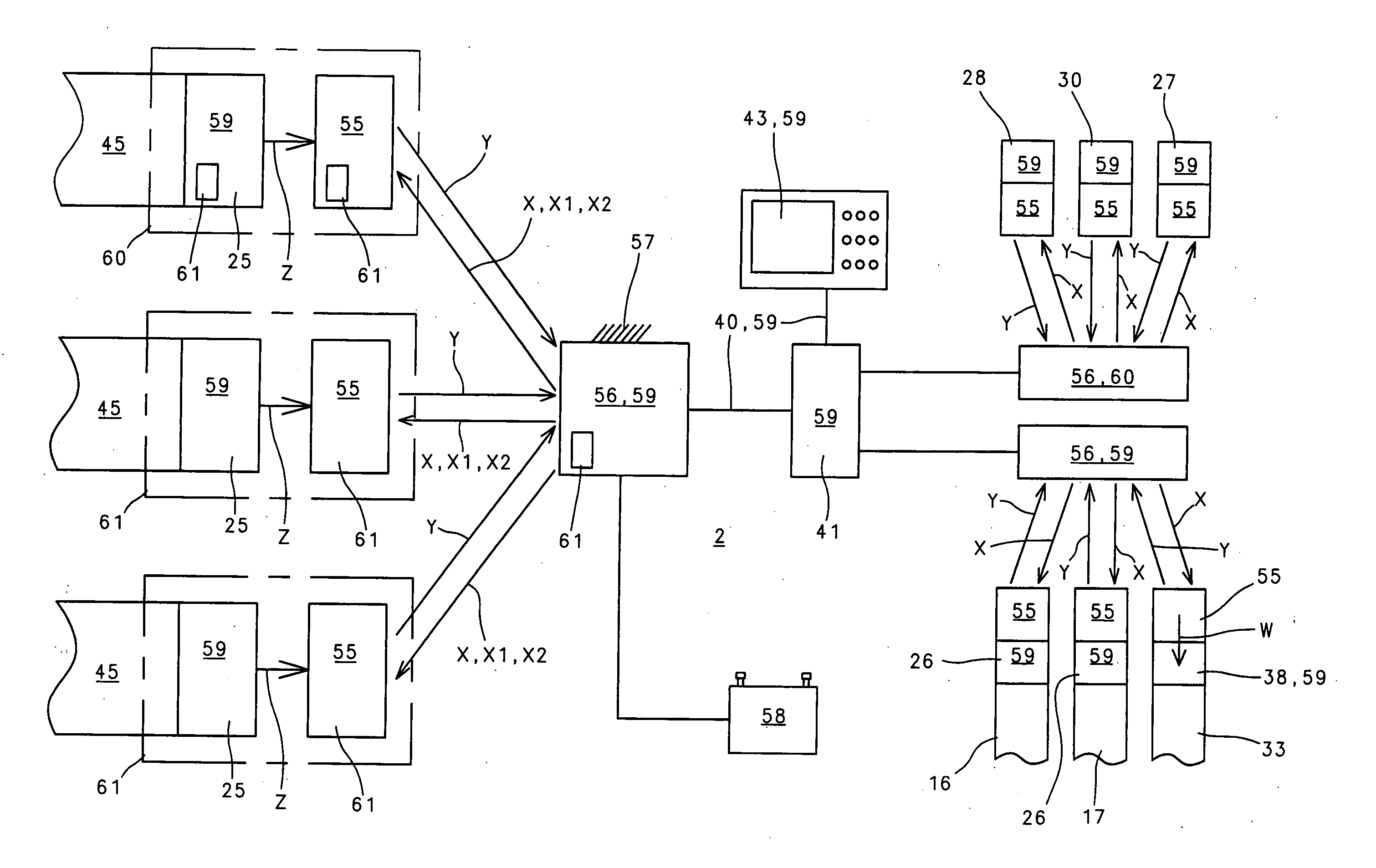
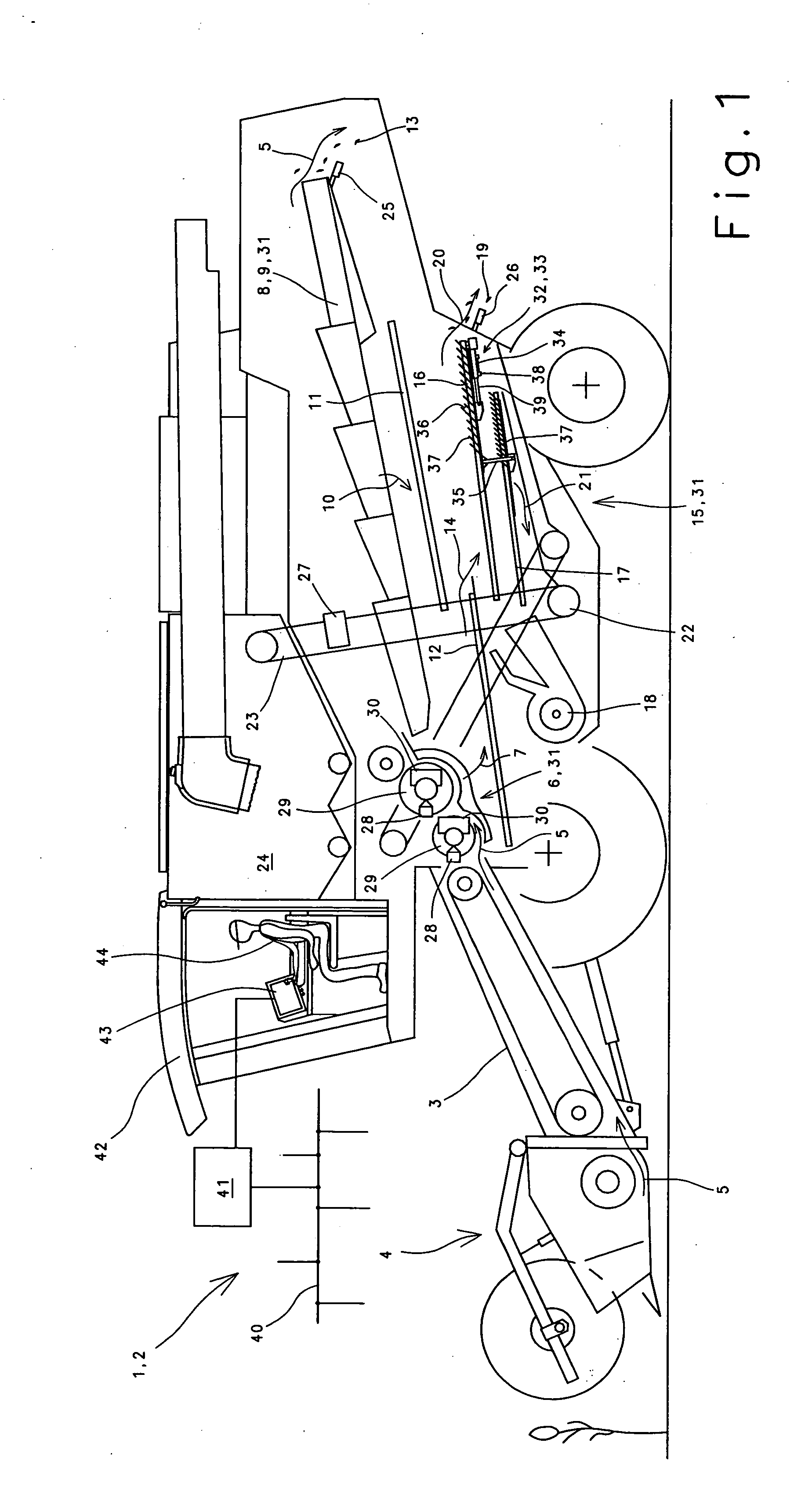
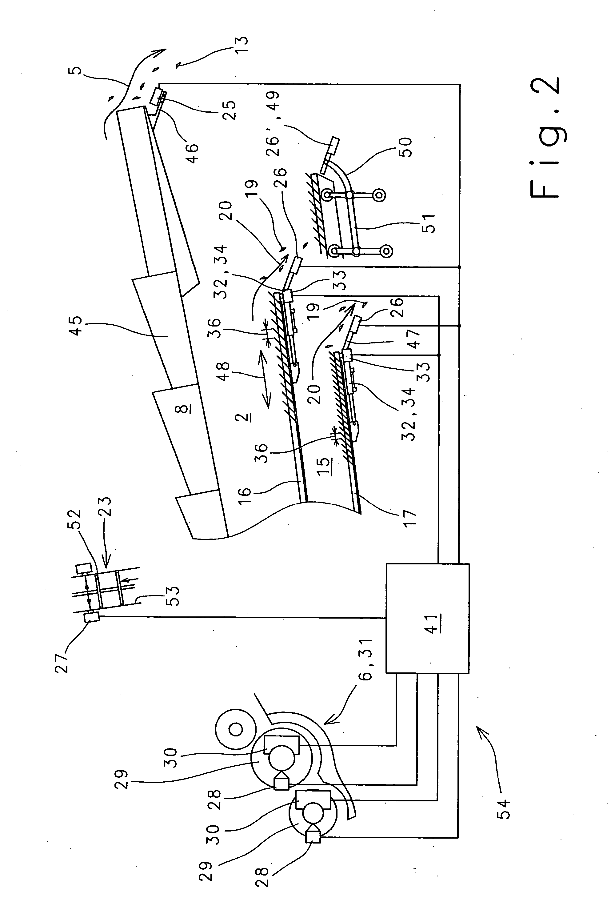
[0031]FIG. 2 shows, for sensors 25-28, 30, 38 described as an example, their attachment to various working units 31 or actuators 32. Grain-loss sensors 25 that sense loss due to separation 13 are detachably connected to individual trays 45 of tray-type shaker 8 using retaining brackets 46. Due to the fact that individual trays 45 move in a manner such that they are offset from each other, it is advantageous to assign a separate grain-loss sensor 25 to each straw walker rack 45. A plurality of grain-loss sensors 25 can also be assigned to each straw walker rack to improve the measuring accuracy of each straw walker rack. In a similar manner, in the exemplary embodiment shown, in a first embodiment, separate grain-loss sensors 26 for determining losses due to cleaning 19 are assigned to upper sieve 16 and lower sieve 17 of cleaning device 15.

second embodiment

[0032] Grain-loss sensors 26 are also attached via retaining brackets 47 to particular sieve 16, 17 and therefore also perform the swinging motion 48 of particular cleaning sieve 16, 17. To improve the sensing accuracy, a large number of grain-loss sensors 26 can be assigned to each cleaning sieve 16, 17 across the width of cleaning sieve 16, 17. In a second embodiment, a single grain-loss sensor system 49 can be assigned to cleaning device 15, which accommodates a large number of grain-loss sensors 26′ and is coupled either via an adapting device 50 with a swing frame 51 of sieve system 16, 17 and therefore reproduces swing motion 48 of cleaning sieves 16, 17 or is fixed directly to the frame in combine harvester 2. Since sieve opening width 36 is usually adjustable for upper sieve 16 and lower sieve 17 independently of each other, a separate adjusting drive 33 is mounted to each cleaning sieve 16, 17 to change sieve opening width 36.

[0033] In the exemplary embodiment shown, grain ...


PUM


Abstract

A data generation and transmission system in agricultural working machines for exchanging data between mobile working units and/or stationary working units, and actuators includes data generation and transmission elements assignable to at least a portion of the working units, at least a portion of the data generation and transmission elements enabling wireless exchange of data, and an energy required for dealing with generating the data and/or transmitting the data, is associated with the data generation and transmission system so as to produce the data in the data generation and transmission system and/or transmit the data by the data generation and transmission system.

Description

BACKGROUND OF THE INVENTION [0001] The present invention relates to a data generation and transmission system in agricultural working machines. [0002] An agricultural working machine designed as a combine harvester to which a remote-controlled system for switching, operating and controlling working units and actuators is assigned is made known in publication DE 196 18 033. To enable uncomplicated signal transmission between the various elements of the switching and control device, wireless data transmission was selected instead of wire-based signal transmission. So that the signals transmitted to the most diverse actuators can now also trigger control and regulating processes, it is provided that the energy supply to the data exchange system be provided by centralized or decentralized energy accumulators, such as batteries. Embodiments of this type have the disadvantage, in particular, that a large number of smaller battery units must be assigned directly to the particular sensor el...

Claims


Application Information

Patent Timeline
IPC IPC(8): G06F19/00
CPCA01D41/127
Inventor DAMMANN, LUDWIG
Owner CLAAS SELBSTFAHRENDE ERNTEMASCHINEN GMBH
Why Eureka
Try Eureka