Processor, microcomputer and method for controlling program of microcomputer
- Summary
- Abstract
- Description
- Claims
- Application Information
AI Technical Summary
Benefits of technology
Problems solved by technology
Method used
Image
Examples
first embodiment
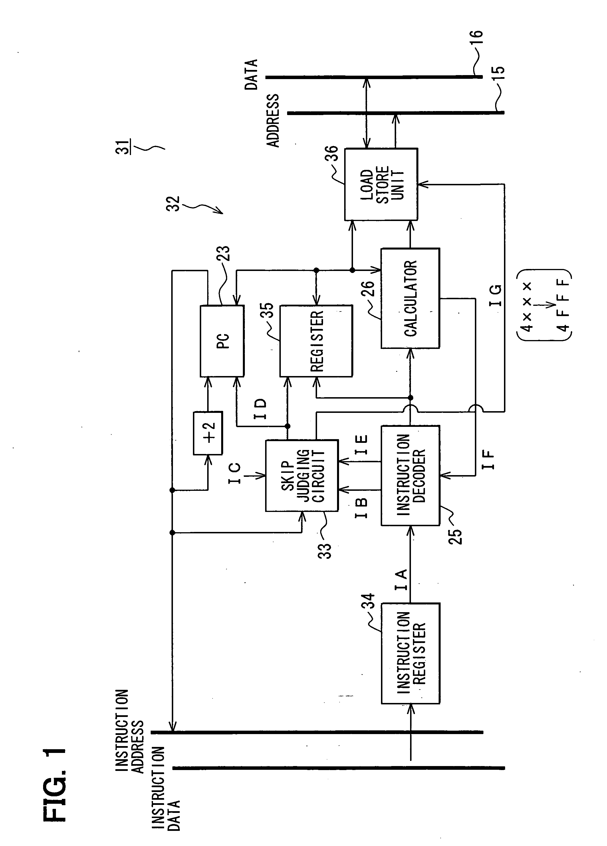
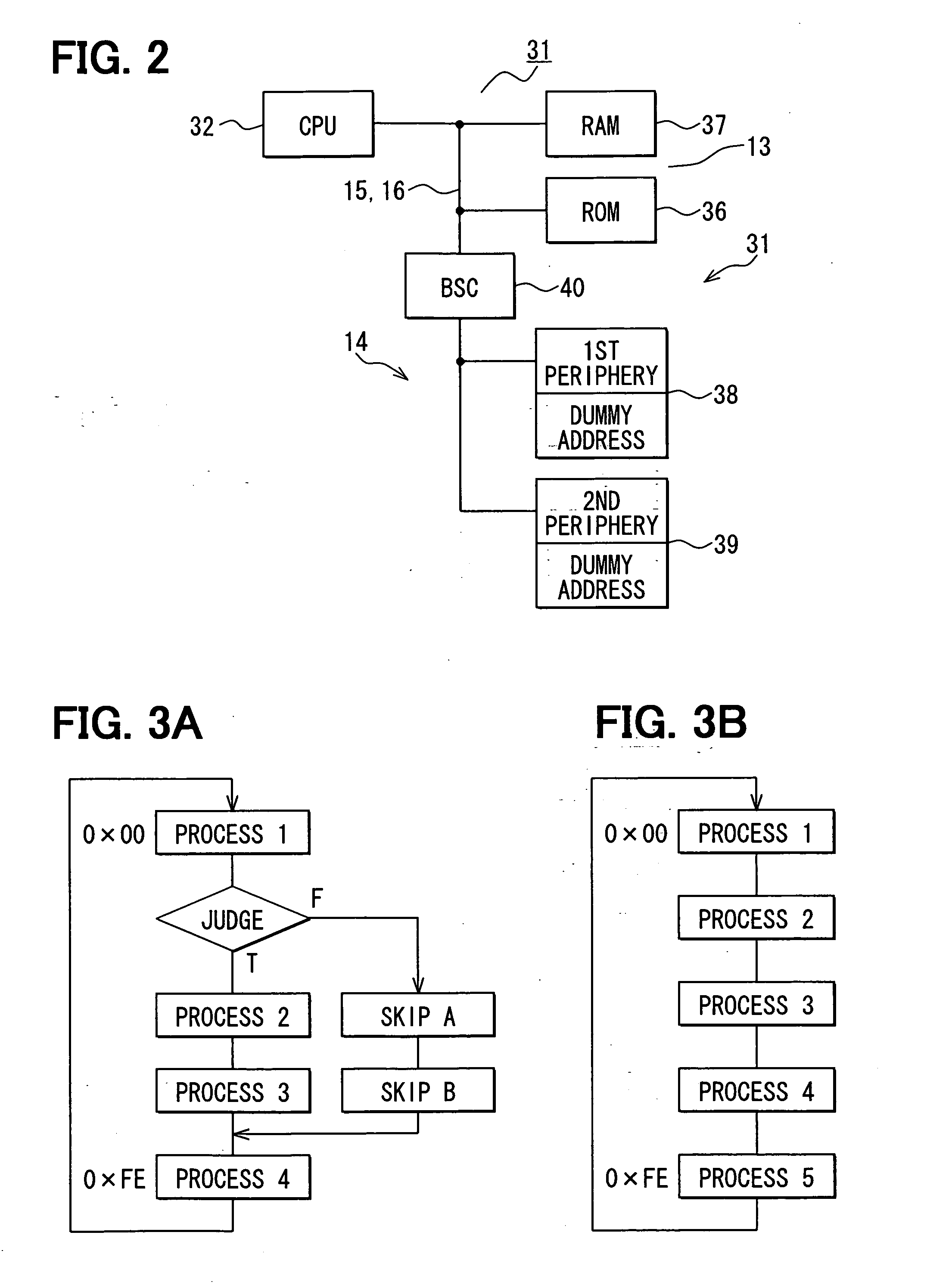
[0066] Referring now to FIG. 1 to FIG. 4B, a first embodiment of the present invention will be described. FIG. 1 is a functional block diagram for indicating an arrangement of a CPU 32 employed in a microcomputer 31 according to the first embodiment of the present invention. In FIG. 1, IA represents an instruction, IB represents a skip signal, i.e., a branching instruction, IC represents a CPU switching signal, ID represents a write inhibit signal, IE represents a load / store instruction, IF represents a condition judging result, and IG represents a switching signal to a dummy address. It should be understood that although a basic arrangement of the CPU 32 is similar to that of the CPU 11 shown in FIG. 5, only structural portions related to the gist of the present invention are extracted to be indicated in FIG. 1, for the sake of easy illustrations. As a novel structural portion provided in the CPU 32, a skip judging circuit 33 is mainly provided in this CPU 32. It should also be not...
second embodiment
[0095] Referring now to FIG. 7 to FIG. 10, a second embodiment of the present invention will be described. FIG. 7 is a functional block diagram for schematically indicating only an arrangement related to the gist of a microcomputer 201 according to the second embodiment of the present invention. Here, in FIG. 7, VIIA represents a branch condition, VIIB represents an interrupt hold, and VIIC represents a branch address. The microcomputer 201 is arranged by a CPU 202, a program memory 203, a data memory 204, a peripheral circuit 205, an interrupt controller 211, and the like.
[0096] The CPU 202 is internally equipped with a program counter (PC) 206, an instruction decoding unit (IDEC) 207, an executing unit (EXE) 208, a register file 209, an interrupt control unit 210, and the like. The instruction decoding unit (IDEC) 207 decodes an instruction fetched from the program memory 203. The executing unit (EXE) 208 executes the instruction decoded by the instruction decoding unit (IDEC) 20...
third embodiment
[0109]FIG. 11 to FIG. 13B indicate a microcomputer 201A according to a third embodiment of the present invention. It should also be understood that the same reference numerals shown in the second embodiment will be employed as those for denoting the same, or similar structural elements indicated in the third embodiment, and explanations thereof are omitted, and thus, only different structural elements of the third embodiment will be explained. FIG. 11 is a functional block diagram for schematically indicating only an arrangement related to the gist of the microcomputer 201A according to the third embodiment of the present invention. Here, in FIG. 11, XIA represents a branch condition, XIB represents an interrupt hold, and XIC represents a branch address. Further, the microcomputer 201A includes a program memory 203A, an interrupt control unit 210A, and an interrupt process program 220A in the program memory 203A. That is, the microcomputer 201A of the third embodiment is arranged in...
PUM
 Abstract
Description
Claims
Application Information
 - R&D
- Intellectual Property
- Life Sciences
- Materials
- Tech Scout
- Unparalleled Data Quality
- Higher Quality Content
- 60% Fewer Hallucinations
Browse by: Latest US Patents, China's latest patents, Technical Efficacy Thesaurus, Application Domain, Technology Topic, Popular Technical Reports.
© 2025 PatSnap. All rights reserved.Legal|Privacy policy|Modern Slavery Act Transparency Statement|Sitemap|About US| Contact US: help@patsnap.com


