Ultraviolet, infrared, and near-infrared lidar system and method

a lidar system and ultra-violet technology, applied in the field of ultra-violet, infrared, and near-infrared lidar systems and methods, can solve the problems of synchronization problems, inability to provide the resolution available with lidar, and inability to provide short-wavelength excitation too

Active Publication Date: 2007-02-01
ARETE ASSOCIATES INC
View PDF4 Cites 68 Cited by
  • Summary
  • Abstract
  • Description
  • Claims
  • Application Information

AI Technical Summary

Benefits of technology

[0039] In particular, inserting the receiving-and-forming means in advance of the time-resolving means can provide to the latter (e. g. a streak tube)—even if the scattered light is not visible light—substantially the same visible optical signal that would be obtained by receiving visible scattered light directly from the objects. The receiving-and-forming means thereby enable the external portions of the overall system to operate in almost any wavelength region; and can free the system from wavelength limitations of the time-resolving means. In this way the heretofore-intractable problems discussed above are substantially eliminated.

Problems solved by technology

Radar, however, simply due to the much longer wavelengths it employs, cannot provide the resolution available with lidar.
(While visible lidar excitation is hazardous because it damages the retina, shorter-wavelength excitation too is hazardous due to damage to the lens of the eye.)
(It will be understood that some very special streak-tube photocathodes have been developed to handle wavelengths other than visible; however, these are not at all commercial materials, and the use of some such photocathode technologies introduces synchronization problems and other drawbacks.)
Severe retinal damage can occur if someone is exposed to radiation transmitted by a conventional streak-tube lidar system.
No streak-tube vendor is currently offering high-quantum-efficiency NIR streak tubes.
Heretofore this has not been practical in the lidar field, even for measurements comparing and contrasting measurements as between the visible and ultraviolet.
As can now be seen, the related art fails to resolve the previously described problems of lidar unavailability for operation outside the visible wavelength region.

Method used


Image

  • Ultraviolet, infrared, and near-infrared lidar system and method
  • Ultraviolet, infrared, and near-infrared lidar system and method
  • Ultraviolet, infrared, and near-infrared lidar system and method

Examples


Embodiment Construction

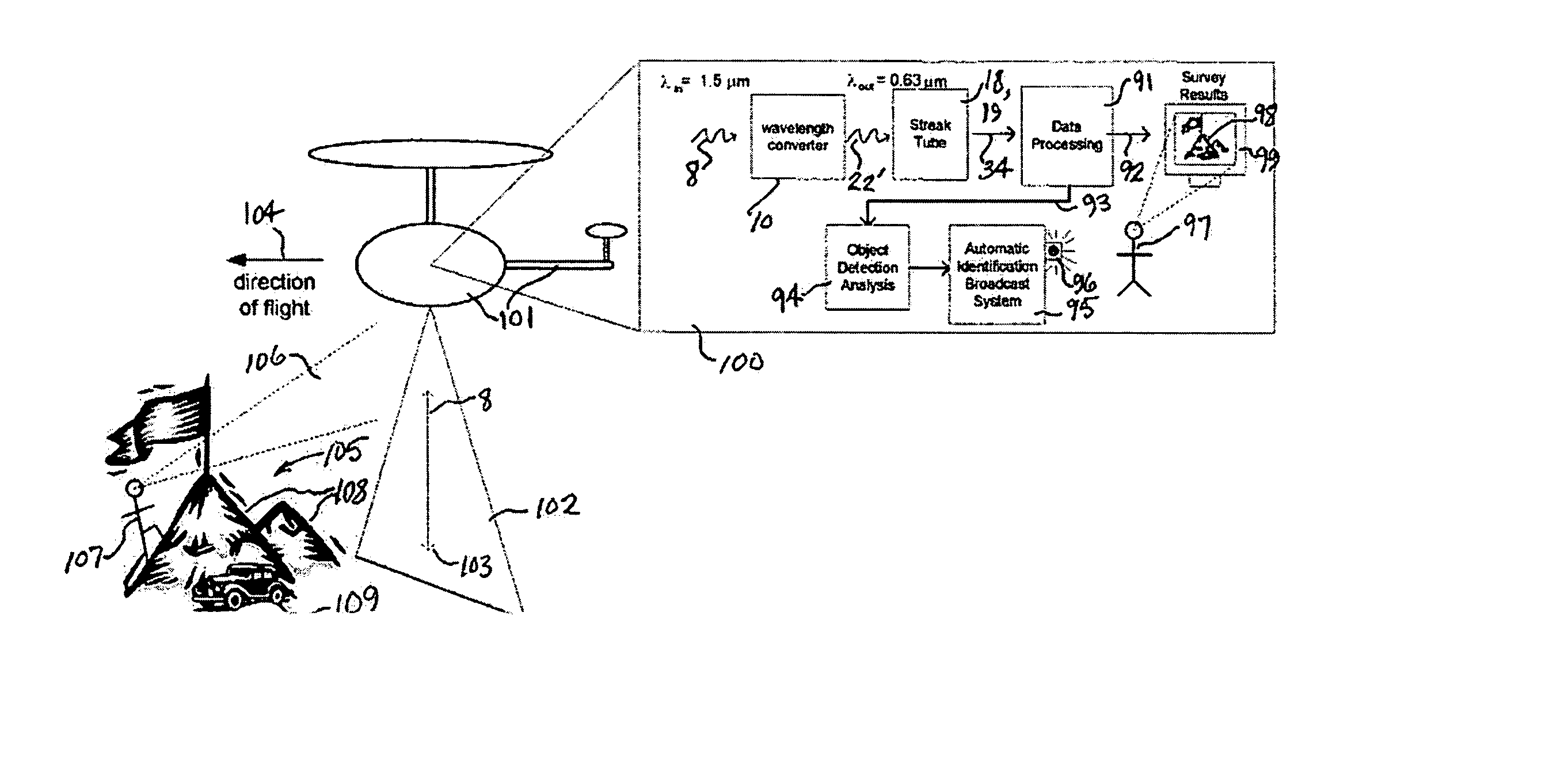
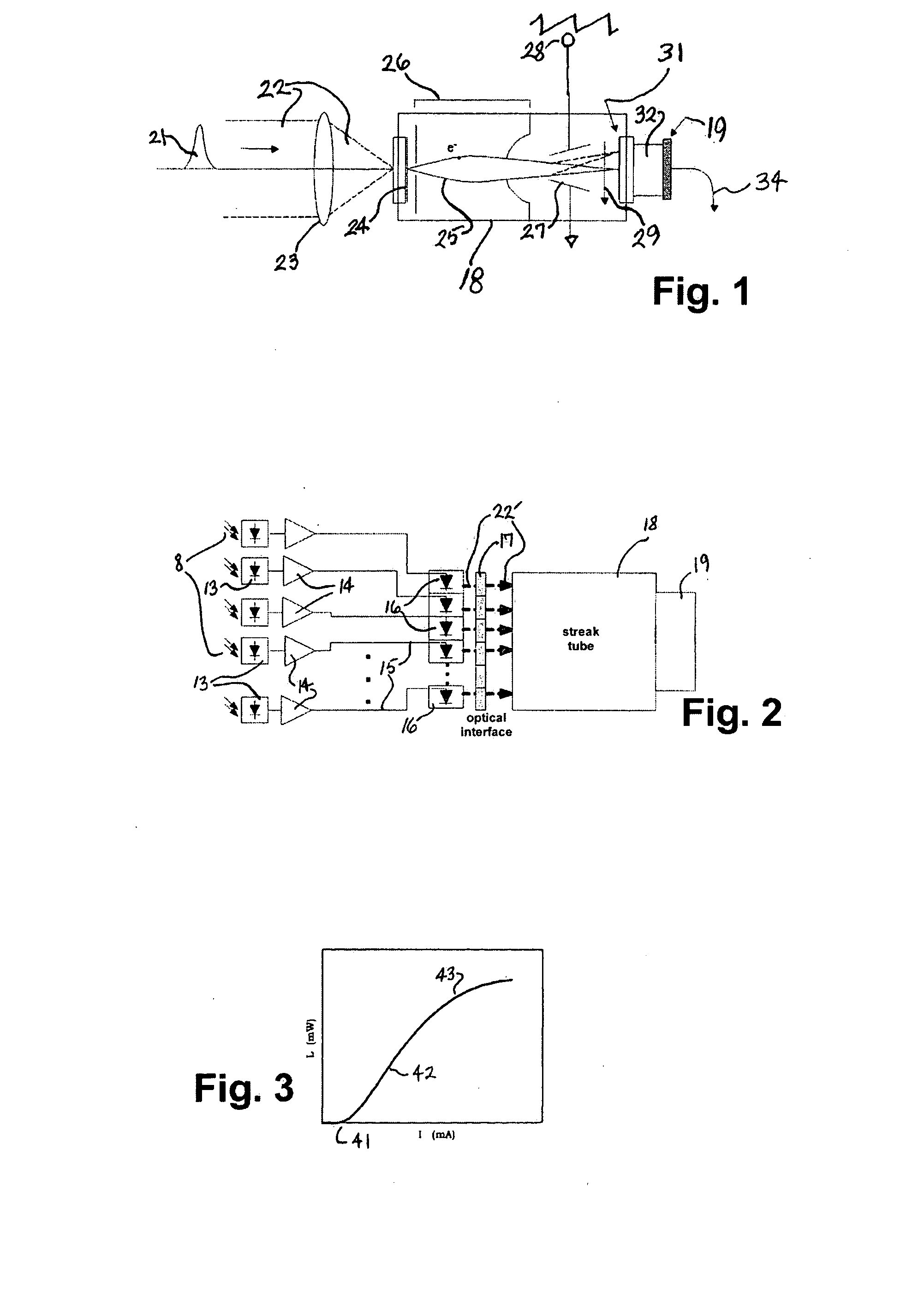
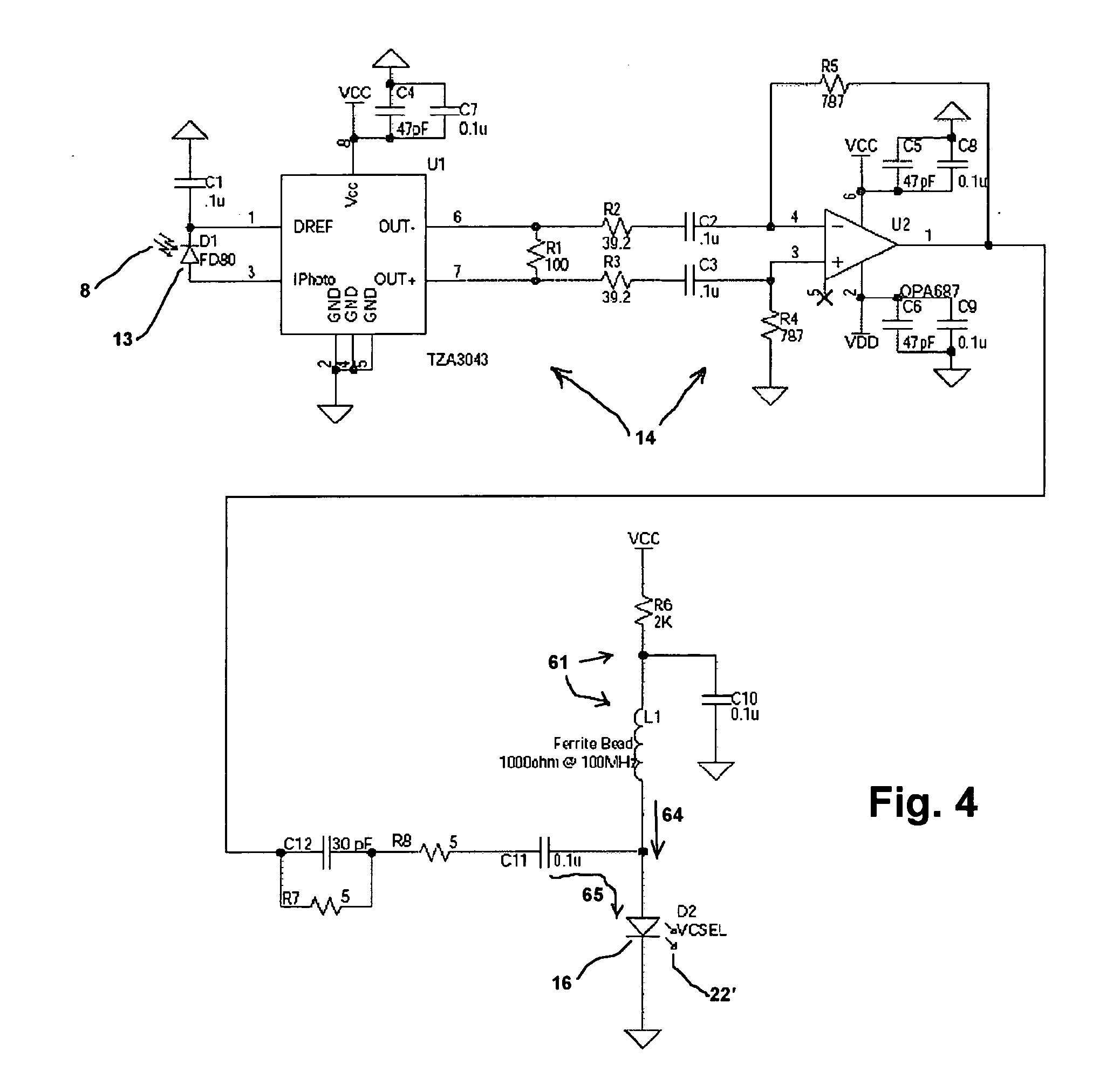
[0107] In preferred embodiments, the invention provides a low-cost alternative to visible-light lidar. NIR radiation pulses can be projected toward objects, and the returned NIR pulses 8 (FIG. 2) converted, at the receiver, into pulses 22′ at a visible wavelength.

[0108] This visible radiation 22′ is then directed into a streak tube 18, effectively emulating the visible light 22 (FIG. 1) entering a streak-tube system conventionally. The remainder of the operation is closely analogous to generally conventional operation of the streak tube, excepting only possible effects of positional quantization along the slit direction—and the result is a streak-tube lidar receiver operable for NIR applications.

[0109] In principle a number of techniques could be used to accomplish the wavelength conversion. It is possible to use nonlinear optical techniques such as Raman scattering, stimulated Raman scattering, and harmonic frequency generation to achieve wavelength conversion. Each of these tech...


PUM


Abstract

Pushbroom and flash lidar operations outside the visible spectrum, most preferably in near-IR but also in IR and UV, are enabled by inserting—ahead of a generally conventional lidar receiver front end—a device that receives light scattered from objects and in response forms corresponding light of a different wavelength from the scattered light. Detailed implementations using arrays of discrete COTS components—most preferably PIN diodes and VCSELs, with intervening semicustom amplifiers—are discussed, as is use of a known monolithic converter. Differential and ratioing multispectral measurements, particularly including UV data, are enabled through either spatial-sharing (e. g. plural-slit) or time-sharing.

Description

[0001] Wholly incorporated by reference herein is the present inventors' coowned U.S. provisional patent application 60 / 440,303, whose priority benefit is hereby asserted. RELATED DOCUMENTS [0002] Closely related documents are other, coowned U.S. utility-patent documents—also incorporated by reference in their entirety. Those documents are: Bowker et al., U.S. Pat. No. 6,400,396 (medical scale) and U.S. Pat. No. 5,467,122 (ocean scale), and Ser. No. 09 / 125,259 (wide range of scales); McLean et al., Ser. No. 09 / 390,48 (shallow angle); Gleckler et al., Ser. No. 10 / 258,917 (plural slit); and Griffis et al., Ser. No. 10 / 426,907 (without streak tube). Other patents and publications of interest are introduced below.FIELD OF THE INVENTION [0003] This invention relates generally to systems and methods for automatically detecting light reflected or scattered from an object, and determining distance to the object. Also found, in preferred applications of the invention, are other properties of...

Claims


Application Information

Patent Timeline
Patent Type & Authority Applications(United States)
IPC IPC(8): G01C3/08G06K9/00
CPCG01S7/4811G01S7/484G01S7/4861G01S17/89G01S7/487
Inventor FETZER, GREGORY J.SITTER, DAVID N. JR.GUGLER, DOUGLASRYDER, WILLIAM L.GRIFFIS, ANDREW J.MILLER, DAVIDGELBART, ASHERBYBEE-DRISCOLL, SHANNON
Owner ARETE ASSOCIATES INC
Why Eureka
Try Eureka