Power saving device and electronic device using the same

Inactive Publication Date: 2006-07-13
ONKYO KK
View PDF7 Cites 18 Cited by
  • Summary
  • Abstract
  • Description
  • Claims
  • Application Information

AI Technical Summary

Benefits of technology

[0007] It is therefore an object of the present invention to provide a power saving device capable of desirably reducing the power consumption of a microcomputer in a standby state.
[0009] The controller periodically repeats the power saving mode and the normal mode while a remote control signal is being received. Therefore, the controller can analyze the remote control signal during the normal mode, while reducing the power consumption during the power saving mode. Thus, it is possible to desirably reduce the average power consumption during the remote control signal receiving period. The intermittent operation is ended when the remote control signal is received completely, and the operation can immediately transition to the power saving mode if the remote control signal contains no instruction that needs to be executed. Thus, it is possible to further reduce the power consumption. It is determined that a remote control signal is received completely not only when the remote control signal is received normally and completely, but it is assumed that a remote control signal is received completely also when the remote control signal is discarded for reasons such as the leader code (or the custom code) being invalid or an interference signal contaminating the remote control signal, whereby the code cannot be analyzed properly.
[0011] Therefore, the controller always stay in the power saving mode until a remote control signal is input, whereby it is possible to further reduce the standby power consumption.
[0013] If the remote control signal is a power-requesting signal, the controller transitions to the normal mode after the intermittent operation, whereby the controller can perform an operation based on the remote control signal. If the remote control signal is a non-power-requesting signal, the controller transitions to the power saving mode after the intermittent operation, whereby it is possible to further reduce the power consumption.
[0017] Until a remote control signal is input, the controller is in the first power saving mode in which the oscillator circuit does not supply the clock signal to the main circuit or the timer circuit. This is because the timer circuit does not need to be operated. Therefore, the controller can desirably reduce the power consumption. During the intermittent operation, the controller is in the second power saving mode in which the clock signal is not supplied to the main circuit but is supplied to the timer circuit. Therefore, it is possible to desirably reduce the power consumption by not supplying the clock signal to the main circuit, while the timer circuit can perform the count operation as the clock signal is supplied to the timer circuit. Thus, it is possible to desirably reduce the average power consumption of the controller.
[0019] The controller stays in the power saving mode until a remote control signal is input. The controller periodically repeats the power saving mode and the normal mode while a remote control signal is being received. Therefore, the controller can analyze the remote control signal during the normal mode, while reducing the power consumption during the power saving mode. Thus, it is possible to desirably reduce the average power consumption of the controller.

Problems solved by technology

Therefore, such a conventional method fails to save the power consumption during the remote control signal receiving period.
With this device, however, the microcomputer is in the normal mode while analyzing a remote control signal, thereby failing to save the power consumption during the remote control signal receiving period.
Moreover, since this device performs the intermittent operation and repeats the normal mode at regular intervals until a remote control signal is received, thereby increasing the average power consumption.
The device can gradually increase the average power consumption by gradually increasing the period of the normal mode in the intermittent operation.
This delays the time at which an operation specified by the remote control signal is started.
Another problem is that the power consumption during the remote control signal receiving period cannot be reduced.

Method used


Image

  • Power saving device and electronic device using the same
  • Power saving device and electronic device using the same
  • Power saving device and electronic device using the same

Examples


Embodiment Construction

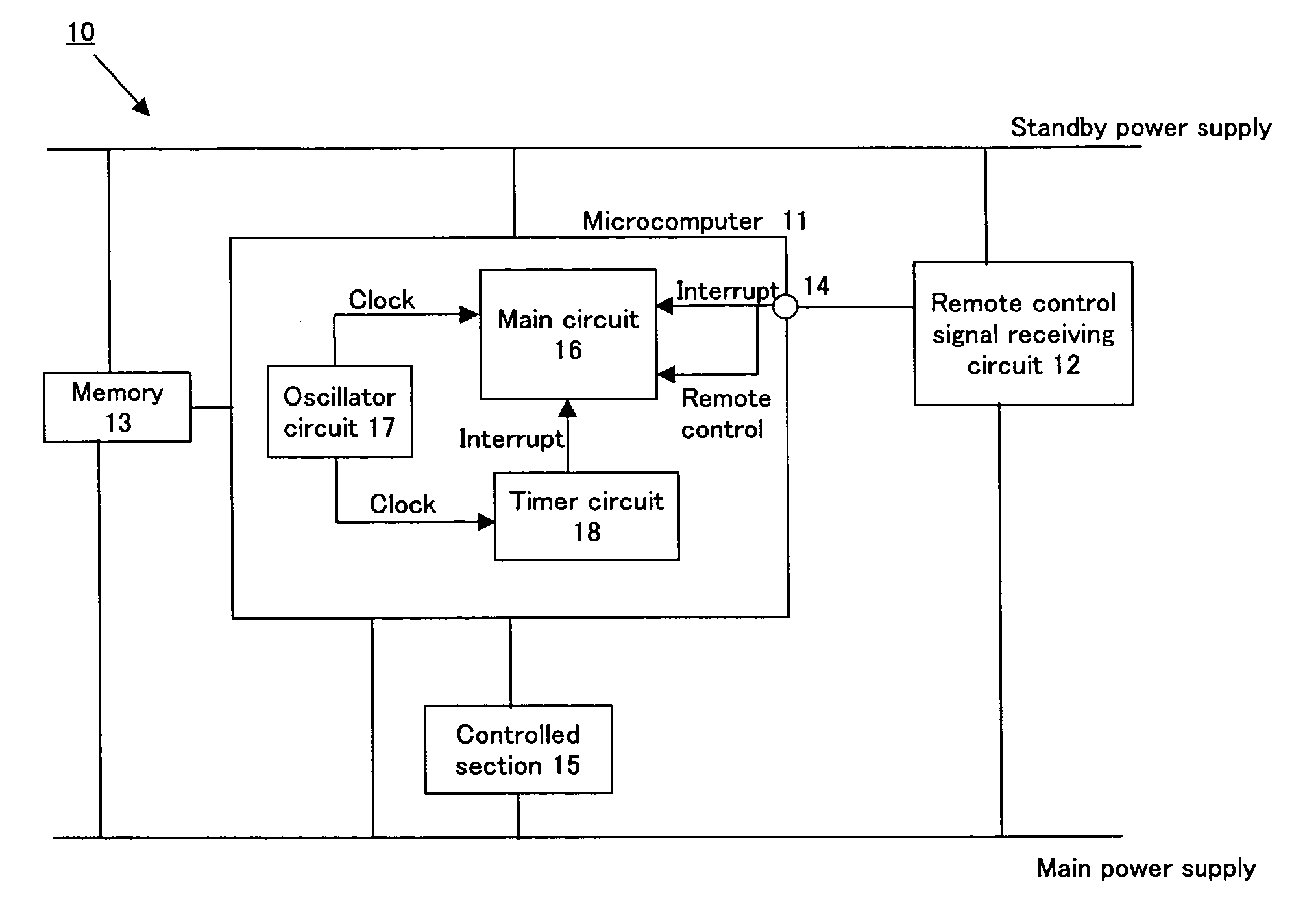
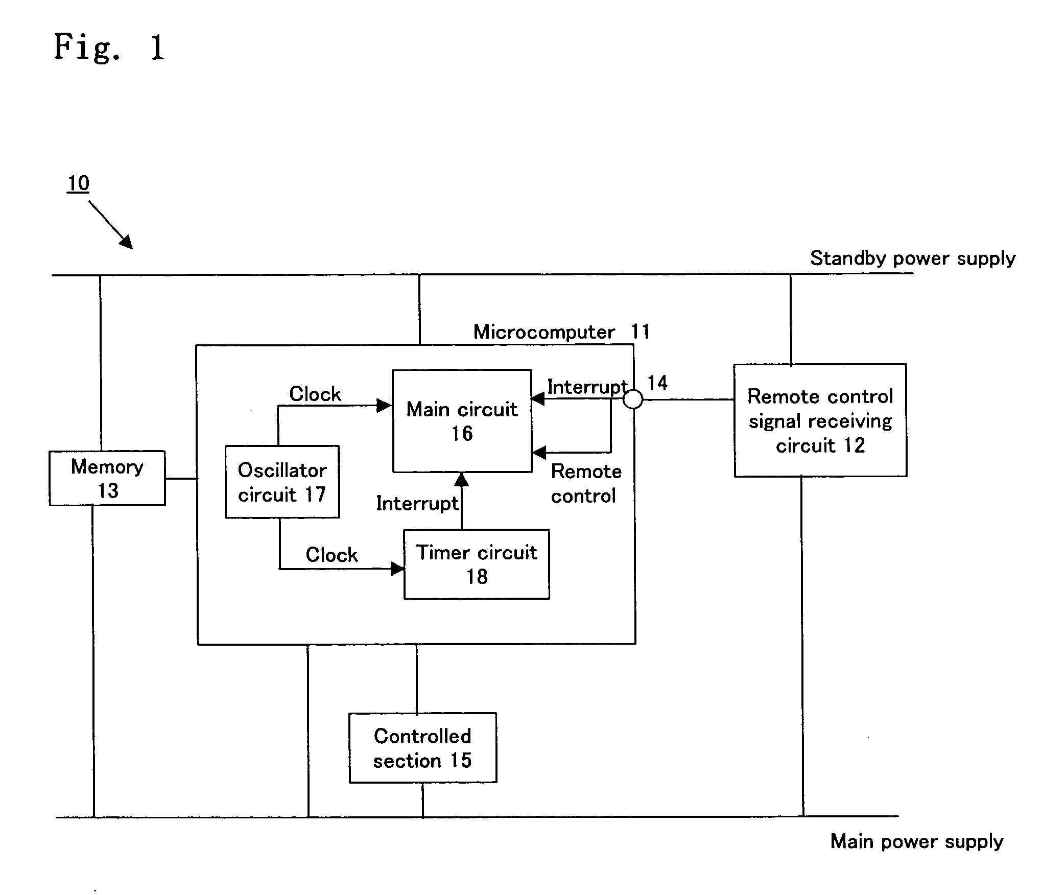
[0023] While a preferred embodiment of the present invention will now be described with reference to the drawings, it is understood that the present invention is not limited thereto. FIG. 1 is a schematic block diagram showing a power saving device 10 according to the preferred embodiment of the present invention. The power saving device 10 includes a controller 11 and a remote control signal receiving circuit 12, and transitions from the power saving mode to the normal mode in response to a received interrupt signal. The power saving device 10 can be used in a common electronic device such as a CD player.

[0024] The controller 11 controls the overall operation of an electronic device (e.g., a CD player) with which the power saving device 10 can be used (i.e., it controls a controlled section 15), and is typically a microcomputer, for example. The microcomputer 11 includes a memory 13 (e.g., a ROM and / or a RAM), which may be provided in the microcomputer 11 or may be provided outsid...


PUM


Abstract

A microcomputer 11 stays in a power saving mode until a remote control signal is input and a first interrupt signal is input to an interrupt terminal 14. When the first interrupt signal is input, the microcomputer 11 performs an intermittent operation in which the power saving mode and the normal mode are periodically alternated with each other, and ends the intermittent operation when the remote control signal is received completely. After the intermittent operation, the microcomputer 11 stays in the normal mode if the remote control signal is a power-requesting signal and stays in the power saving mode otherwise.

Description

BACKGROUND OF THE INVENTION [0001] 1. Field of the Invention [0002] The present invention relates to a power saving device in which a microcomputer is shut down in a standby state. [0003] 2. Description of the Related Art [0004] An electronic device such as an AV device has a standby state, where power is supplied only to the microcomputer and to the peripheral circuits thereof so that the power of the device can be turned back ON in response to a user's operation of a remote control even when the power of the device is OFF. Recently, there is a demand for further reducing the standby power consumption, i.e., the amount of power to be consumed in a standby state. In view of such a demand, the microcomputer has a power saving mode in which the microcomputer itself is shut down when the microcomputer has no process to execute. Then, in response to a remote control signal, an interrupt signal is input to an interrupt terminal of the microcomputer for triggering a transition from the po...

Claims


Application Information

Patent Timeline
IPC IPC(8): G06F1/26G06F1/32
CPCG06F1/3203
Inventor ITO, KAZUNARISUNAGA, TADAHARU
Owner ONKYO KK
Why Eureka
Try Eureka