Reduced maintenance sputtering chambers

a sputtering chamber and maintenance technology, applied in the direction of vacuum evaporation coating, electrolysis components, coatings, etc., can solve the problems of significant loss of coating, difficult and time-consuming removal, and significant overcoating, so as to reduce the amount of unwanted sputtering and overcoating

Inactive Publication Date: 2006-07-20
CARDINAL CG
View PDF0 Cites 7 Cited by
  • Summary
  • Abstract
  • Description
  • Claims
  • Application Information

AI Technical Summary

Benefits of technology

[0007] In a second chamber according to the present invention, improved spall shields are provided. The spall shields can be oriented upwardly and inwardly toward the chamber interior and toward the targets within the chamber interior. The upwardly and inwardly oriented spall shields can serve to retain overcoat sputtering material which might otherwise flake off and drop onto substrates to be coated. In one chamber according to this aspect of the invention, the spall shields curve upwardly and inwardly, and have an arcuate shape terminating in a tip. In another embodiment, the spall shields form a continuous arcuate curve with the side walls of the chamber. In yet another embodiment, the spall shields are substantially straight, having a straight portion extending upwardly and inwardly toward the chamber interior.
[0008] In a third aspect of the intention, a third target can be disposed upwardly and between the lower first and second targets. The third target can serve to shield an upper portion of the sputtering chamber interior from sputtering material deposited by the first and second targets below. The third, upper target can be the same size or a different size relative to the first and second targets below. The third target is preferably closely spaced to the first and second target to reduce the amount of unwanted sputtering and overcoating on the chamber interior. In one embodiment, the first and second, lower targets have arcuate magnets oriented inwardly relative to vertical, while the third, upper magnet is oriented vertically downward. The second and third target can shield a portion of the chamber interior from the first target, and the first and third target can shield a portion of the chamber from the second target. In one embodiment, the first, second, and third targets form an isosceles triangle. In another embodiment, the first, second and third targets form an equilateral triangle. In one embodiment, at least one of the targets is cantilevered off of a front or rear wall. In another embodiment, the lower, first and second targets are cantilevered off of a rear wall, while the third, upper target is cantilevered off of a front wall.

Problems solved by technology

This is sometimes referred to as “overcoating.” Overcoating is a significant problem for a number of reasons.
As noted above, it accounts for a significant amount of lost coating.
Removal is difficult and time-consuming.
Removal can cause process downtime periods lasting several hours or more which is terribly economically inefficient.
In addition, the overcoated material deposited on the interior surfaces of a sputtering chamber tends to exhibit spalling during the heating and cooling cycles that are typically experienced by sputtering chambers.
For example, the overcoated surfaces of a vacuumized sputtering chamber tend to heat up during sputtering.
These flakes of overcoat can fall upon the substrate being coated, causing damage through inclusions, pinholes, and other defects to the coating deposited on the substrate.
Thus, once a chamber is shut down and flakes of sputtered material begin to fall, sputtering is typically not resumed until the shower of spalling flakes subsides.
Unfortunately, flakes of sputtering material may spall from the interior surfaces of a sputtering chamber for significant periods of time, which can be on the order of one to two hours in some cases.
As industrial sputtering lines are extraordinarily expensive, the productivity lost by this added down time is terribly inefficient and costly.

Method used


Image

  • Reduced maintenance sputtering chambers
  • Reduced maintenance sputtering chambers
  • Reduced maintenance sputtering chambers

Examples


Embodiment Construction

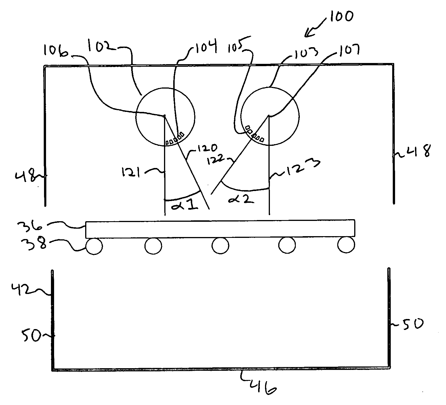
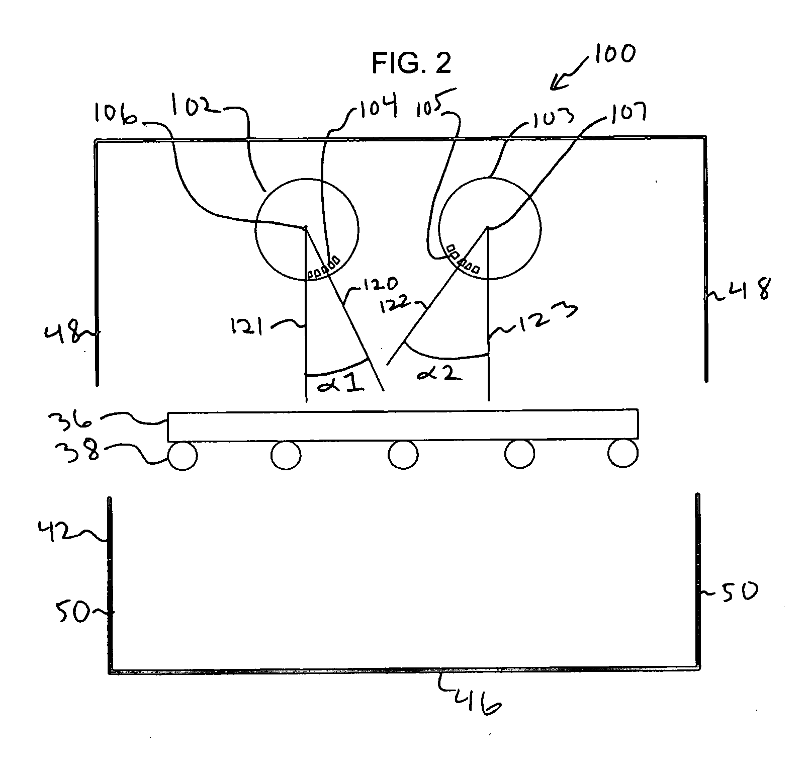
[0017] The following detailed description should be read with reference to the drawings, in which like elements in different drawings are numbered identically. The drawings, which are not necessarily to scale, depict selected embodiments and are not intended to limit the scope of the invention. Several forms of invention have been shown and described, and other forms will now be apparent to those skilled in art. It will be understood that embodiments shown in drawings and described above are merely for illustrative purposes, and are not intended to limit scope of the invention as defined in the claims which follow.

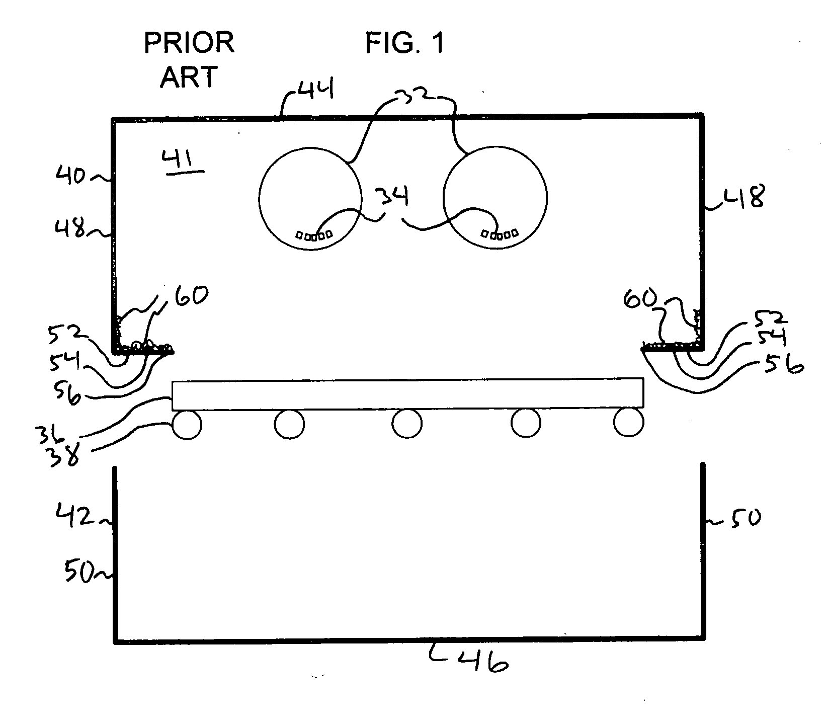
[0018]FIG. 1 illustrates a prior art sputtering chamber 30 having a top portion 40 and a bottom portion 42. Top portion 40 includes generally an interior 41, a ceiling 44, side walls 48, and lower ledges or spall shields 52. Spall shield 52 may be seen to have an inward-most extent or tip 56 and a ledge portion 54. Spall shields 52 may be seen to be substantially horizont...


PUM

PropertyMeasurementUnit
anglesaaaaaaaaaa
anglesaaaaaaaaaa
anglesaaaaaaaaaa

Abstract

Improved sputtering chambers for sputtering thin coatings onto substrates. One sputtering chamber includes spall shields which are disposed inwardly and upwardly toward the chamber interior and toward the sputtering targets, and which can aid in the retention of overcoated sputtering material which may otherwise fall onto substrates to be coated. Another sputtering chamber includes targets having magnets which are turned inwardly relative to vertical and toward each other. The inward rotation of the magnets can serve to deposit more material toward the open bottom center of the chamber, and less toward the side walls of the chamber. Yet another sputtering chamber includes a third target disposed between and upward of the lower two targets so as to shield a portion of the sputtering chamber interior from material sputtered from the first and second targets. Some chambers have the three targets forming a triangle, for example, an isosceles or equilateral triangle. In one chamber having such a triangular configuration of sputtering targets, the first and second targets form the base of an isosceles triangle and have their magnets oriented inwardly relative to vertical and towards each other. The sputtering chambers provided can either reduce the amount of overcoat sputtering material deposited onto the interior of the chamber and/or aid in retention of overcoat sputtering material which would otherwise fall onto substrates to be coated.

Description

FIELD OF THE INVENTION [0001] The present invention relates generally to methods and devices for magnetron sputtering of material onto substrates. More particularly, the present invention relates to improved sputtering chamber designs. BACKGROUND OF THE INVENTION [0002] Sputter deposition is a process for applying thin films onto substrates. Generally, the sputtering process occurs within a sputtering chamber within which a controlled environment can be established. A target or targets including a material to be deposited can be positioned within the sputtering chamber, and a power supply connected to the target to apply a cathodic charge to at least portions of the target. A relatively positively charged anode can be positioned within the sputtering chamber proximate the target. The chamber is evacuated and a plasma gas established within the chamber. Ions of the plasma gas are accelerated by electrical charges into the targets, causing particles of the targets to be physically eje...

Claims


Application Information

Patent Timeline
Patent Type & Authority Applications(United States)
IPC IPC(8): C23C14/00
CPCC23C14/352C23C14/564H01J37/32477H01J37/32871H01J37/3405H01J37/3455
Inventor HARTIG, KLAUS
Owner CARDINAL CG
Why Eureka
Try Eureka