

Vacuum hold-down
- Summary
- Abstract
- Description
- Claims
- Application Information
AI Technical Summary
Benefits of technology
Problems solved by technology
Method used
Image

Examples
Embodiment Construction
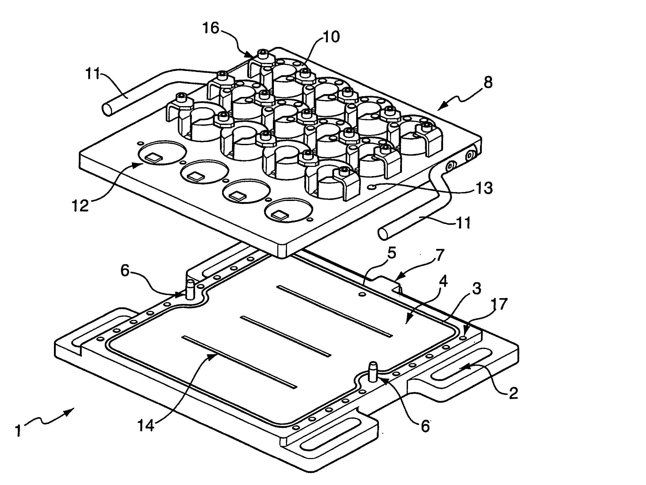
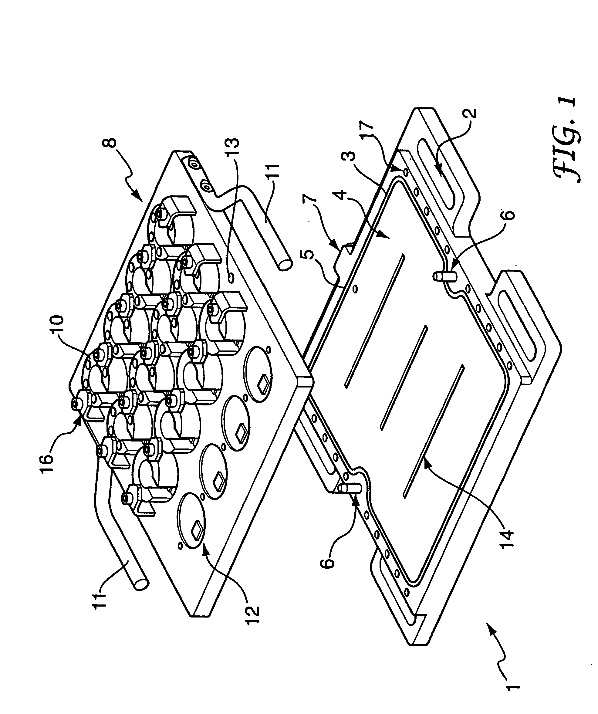
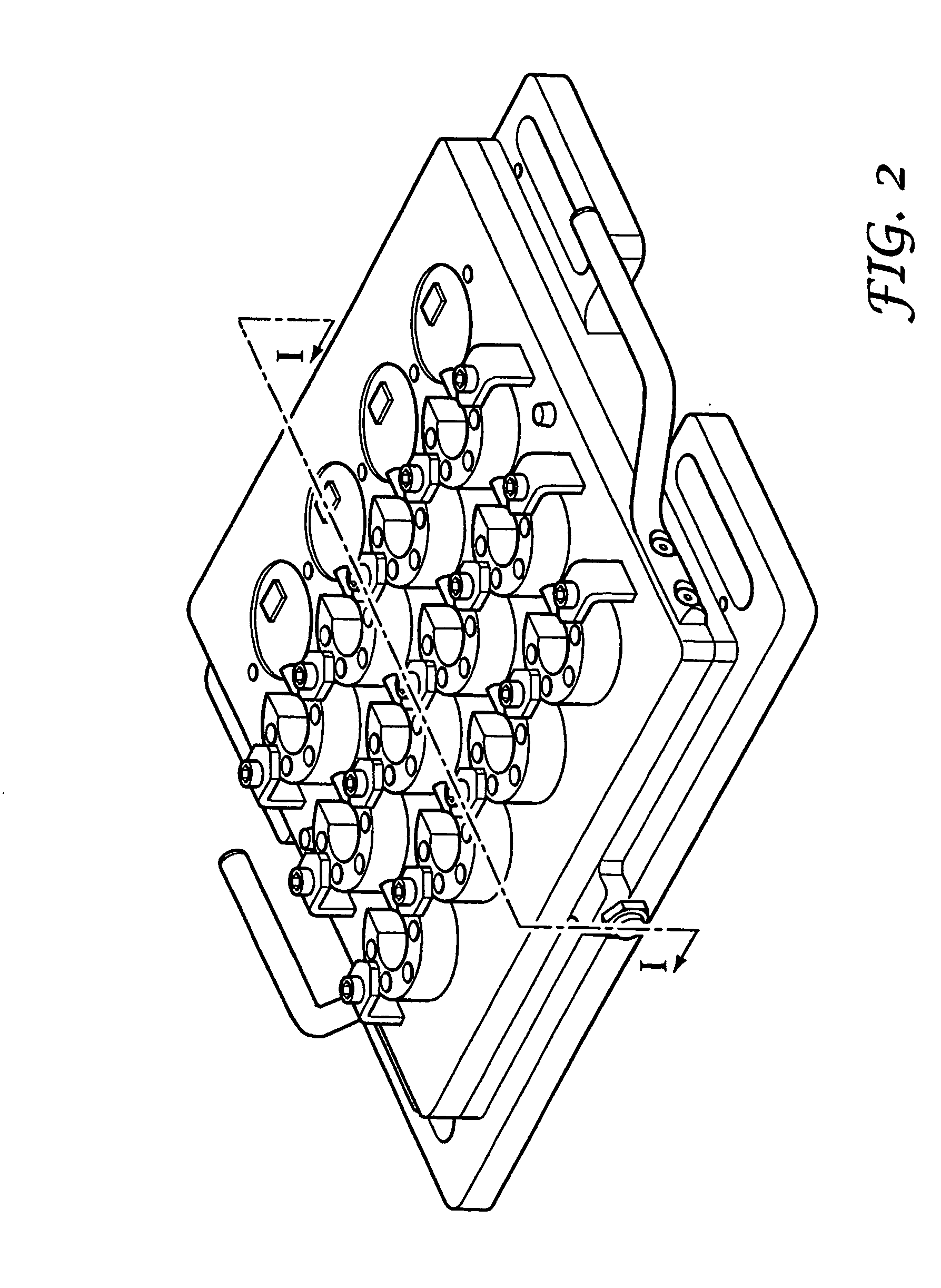
[0030] The vacuum hold-down device shown in FIGS. 1-3 comprises a base plate 1 and a work plate 8 which co-operate to define a vacuum chamber. The base plate 1 is typically formed from a metal, for example steel or aluminium; however other metals may be employed, or structural plastics materials.
[0031] The base plate 1 has integral slots 2 formed therein, for clamping it to an existing machine bed or table. Locating dowels 17 permit precise, square location of the base plate on the machine table prior to clamping. The upper surface of base plate 1 has a slightly recessed region 4, surrounded by an O-ring seal 3 for co-operating with the inner (lower) surface of the work plate 8 to define the vacuum chamber. It will be understood that the recessed region could alternatively be provided on the lower surface of the work plate 8, or on both plates. A pair of location dowels 6 are provided on the base plate 1, which fit in corresponding location holes 13 in the workpiece support to ensu...
PUM
 Abstract
Description
Claims
Application Information