Antenna using inductively coupled feeding method, RFID tag using the same and antenna impedence matching method thereof

a technology of inductive coupling and antenna, applied in the field of antenna, can solve the problems of difficulty in miniaturization and cost, inability to unconditionally raise the transmission power level, etc., and achieve the effect of small size, low cost, and effective matching

Inactive Publication Date: 2006-07-20
ELECTRONICS & TELECOMM RES INST
View PDF16 Cites 220 Cited by
  • Summary
  • Abstract
  • Description
  • Claims
  • Application Information

AI Technical Summary

Benefits of technology

[0005] It is, therefore, an object of the present invention to provide an antenna which is smal

Problems solved by technology

However, since the transmission power of the reader is limited by local regulation of each country including the Federal Communication Commission (FCC) of the U.S.A., it is not possible to unconditionally raise the level of transmission power

Method used


Image

  • Antenna using inductively coupled feeding method, RFID tag using the same and antenna impedence matching method thereof
  • Antenna using inductively coupled feeding method, RFID tag using the same and antenna impedence matching method thereof
  • Antenna using inductively coupled feeding method, RFID tag using the same and antenna impedence matching method thereof

Examples


Embodiment Construction

[0021] Other objects and advantages of the present invention will become apparent from the following description of the embodiments with reference to the accompanying drawings. Therefore, those skilled in the art that the present invention is included can embody the technological concept and scope of the invention easily. In addition, if it is considered that detailed description on the prior art may blur the points of the present invention, the detailed description will not be provided herein. The preferred embodiments of the present invention will be described in detail hereinafter with reference to the attached drawings.

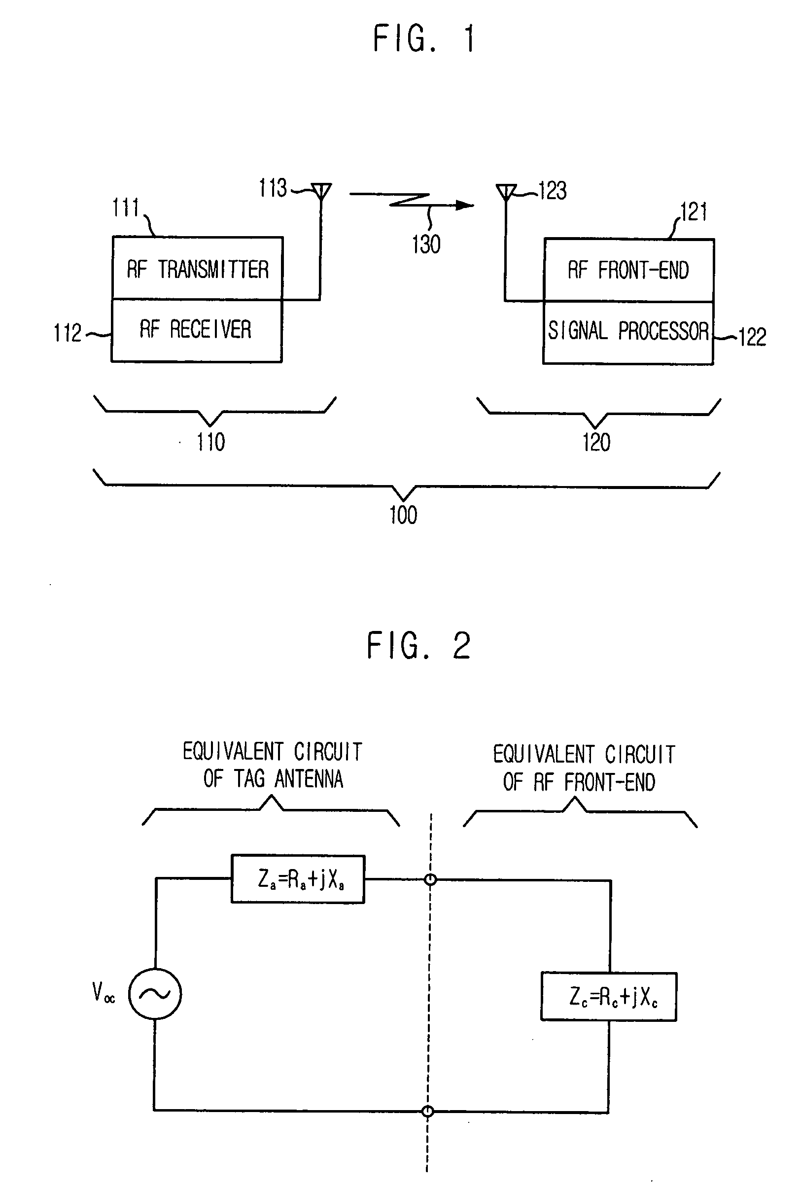
[0022]FIG. 1 is a block diagram showing a Radio Frequency Identification (RFID) system to which the present invention is applied.

[0023] The RFID system 100 includes an RFID tag 120 for storing unique information, an RFID reader 110 having reading and decoding functions, and a host computer (not shown in FIG. 1) for processing data read from the RFID tag 120 thro...


PUM


Abstract

Provided are an antenna using an inductively coupled feeding method, a Radio Frequency Identification (RFID) tag thereof, and an antenna impedance matching method thereof. The antenna includes a resonator for determining a resonance frequency of the antenna and a feeder for providing an RF signal to an element connected to the antenna. An RFID tag includes an antenna which receives an RF signal from the RFID reader, an RF front-end which rectifies and detects the RF signal, and a signal processor which is connected to the RF front-end. Particularly, the antenna includes a resonator for determining a resonance frequency of an antenna and a feeder for providing the RF signal to the RF front-end, wherein mutual inductive coupling between the resonator and the feeder is performed.

Description

FIELD OF THE INVENTION [0001] The present invention relates to an antenna, a Radio Frequency Identification (RFID) tag using the same and an antenna impedance matching method; and, more particularly, to an antenna using an inductively coupled feeding method, an RFID tag equipped with the antenna and an antenna impedance matching method. Description of Related Art [0002] A Radio Frequency Identification (RFID) tag is used in diverse fields such as materials management and security together with an RFID reader. Generally, when an object with the RFID tag is put in a read zone of the RFID reader, the RFID reader transmits an interrogation signal to the RFID tag by modulating an RF signal having a specific carrier frequency and the RFID tag responses to the interrogation of the RFID reader. That is, the RFID reader transmits an interrogation signal to the RFID tag by modulating a continuous electromagnetic wave having a specific frequency, and the RFID tag transmits back the electromagn...

Claims


Application Information

Patent Timeline
IPC IPC(8): H01Q7/00G08B13/14
CPCH01Q1/22H01Q1/2225H01Q1/38H01Q7/00
Inventor SON, HAE-WONCHOI, WON-KYUYUN, JE-HOONPYO, CHEOL-SIGCHAE, JONG-SUK
Owner ELECTRONICS & TELECOMM RES INST
Why Eureka
Try Eureka