Collimated ionizers with fans

a technology of collimated ionizers and fans, applied in the field of collimated ionizers, can solve the problems of limiting the available benefit, unable to perform useful work, and fans alone miss the opportunity for even better ionizer performance, and achieve the effect of reducing the discharge tim

Active Publication Date: 2006-07-20
ILLINOIS TOOL WORKS INC
View PDF7 Cites 5 Cited by
  • Summary
  • Abstract
  • Description
  • Claims
  • Application Information

AI Technical Summary

Benefits of technology

The patent text shows that using a collimator can help reduce the time it takes to discharge a device. The text also explains how different design parameters can affect this. The technical effect of this is that using a collimator can improve the speed and efficiency of devices.

Problems solved by technology

The technical problem addressed in this patent text is the improvement of ionizer performance by reducing recombination and grounding of air ions, and optimizing the use of fans to carry the ions towards the target. The current solutions, such as using fans, have limitations such as producing turbulent air, increasing recombination, and wasting ions. The patent proposes modifications to the fans to overcome these limitations and achieve better ionizer performance.

Method used


Image

  • Collimated ionizers with fans
  • Collimated ionizers with fans
  • Collimated ionizers with fans

Examples


Embodiment Construction

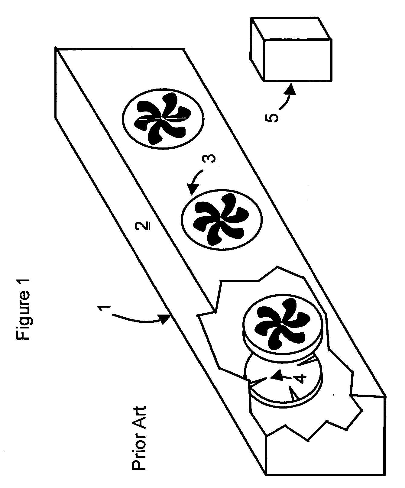
[0028]FIG. 1 shows a prior art ionizer with fans 1. Inside the chassis 2, air ions are created by high voltage applied to the corona electrodes 4. A fan 3 pulls the ions from the corona electrodes 4, and blows them toward a target 5. This ionizer with fans incorporated is a significant improvement over ionizers without fans. Static charge can be removed within practical time periods at large distances when the fans are incorporated. For example, a 20 nanoCoulomb charge 30 inches from the ionizer with fans is typically reduced to 2 nanoCoulombs within 5 seconds. Without the fans, the same charge removal depends on room air currents and may require more than 30 seconds.

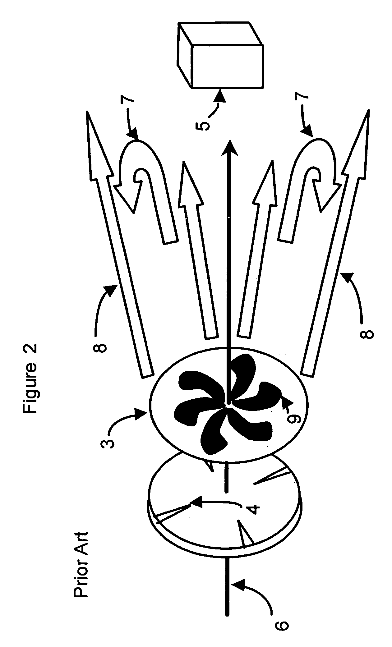
[0029] However, the use of fans does not give the optimal charge removal performance. Fans introduce problems of their own as shown in FIG. 2. For example, although the axial flow line 6 is pointed toward the target 5, turbulence 7 facilitates the loss of air ions by mixing and recombination. In addition, air ions caug...


PUM


Abstract

An air ion collimator is added to ionizers with integrated fans that are used to remove static charge. Three mechanisms minimize air ion losses through recombination. Hence, the collimator increases the air ions that are available for charge removal. First, reducing turbulence slows air ion mixing. Second, air entrainment into fast moving air ion zones further slows the rate of air ion losses by dilution. The rate of recombination reaction slows with decreasing ion density. Third, vanes within the collimator delay mixing. In addition to conserving air ions, the collimator directs more ions to the target. Air ions lost to grounding are reduced. Again, more air ions are available to remove static charge from the target.

Description


Claims


Application Information

Patent Timeline
Owner ILLINOIS TOOL WORKS INC
Why Eureka
Try Eureka