
Magneto-optical disc device and method for writing data on magneto-optical disc

a magnetic disc and optical disc technology, applied in the direction of digital signal error detection/correction, instruments, recording signal processing, etc., can solve the problems of shortening the time required for and affecting the overall write operation.

Inactive Publication Date: 2006-07-20
FUJITSU LTD
View PDF5 Cites 23 Cited by
  • Summary
  • Abstract
  • Description
  • Claims
  • Application Information

AI Technical Summary

Benefits of technology

[0045] It is preferable that the above data write method comprise a counting step of counting the number of executions of the data write processing and data verify processing, and a reference value modification step

Problems solved by technology

However, in this write operation, if a data write operation is performed using laser light with the same power output over a plurality of sectors, depending on the type of magneto-optical disc, errors may occur during execution of verify processing.
In this case, if the magneto-optical disc is irradiated with laser light at the same output power to perform verify processing in the magneto-optical disc device, the same error occurs, and so the laser light output power is switched and verify processing is again executed.
However, as indicated in FIG. 11, if an error is detected during the verify processing, the verify processing is interrupted.
Hence there is the problem that the time required for the overall write operation is lengthened.
In particular, when the number of error occurrences increases, the number of times verify processing is interrupted also increases, and consequently the rotation wait time is also increased, so that the tendency toward longer processing times becomes prominent.
Hence there is the possibility that unnecessary erase processing and write processing is performed for a sector following a sector in which an error has occurred, and in this respect also, the overall time for data writing is lengthened.

Method used


Image

  • Magneto-optical disc device and method for writing data on magneto-optical disc
  • Magneto-optical disc device and method for writing data on magneto-optical disc
  • Magneto-optical disc device and method for writing data on magneto-optical disc

Examples


Embodiment Construction

[0060] Preferred embodiments of the invention will now be described with reference to the drawings.

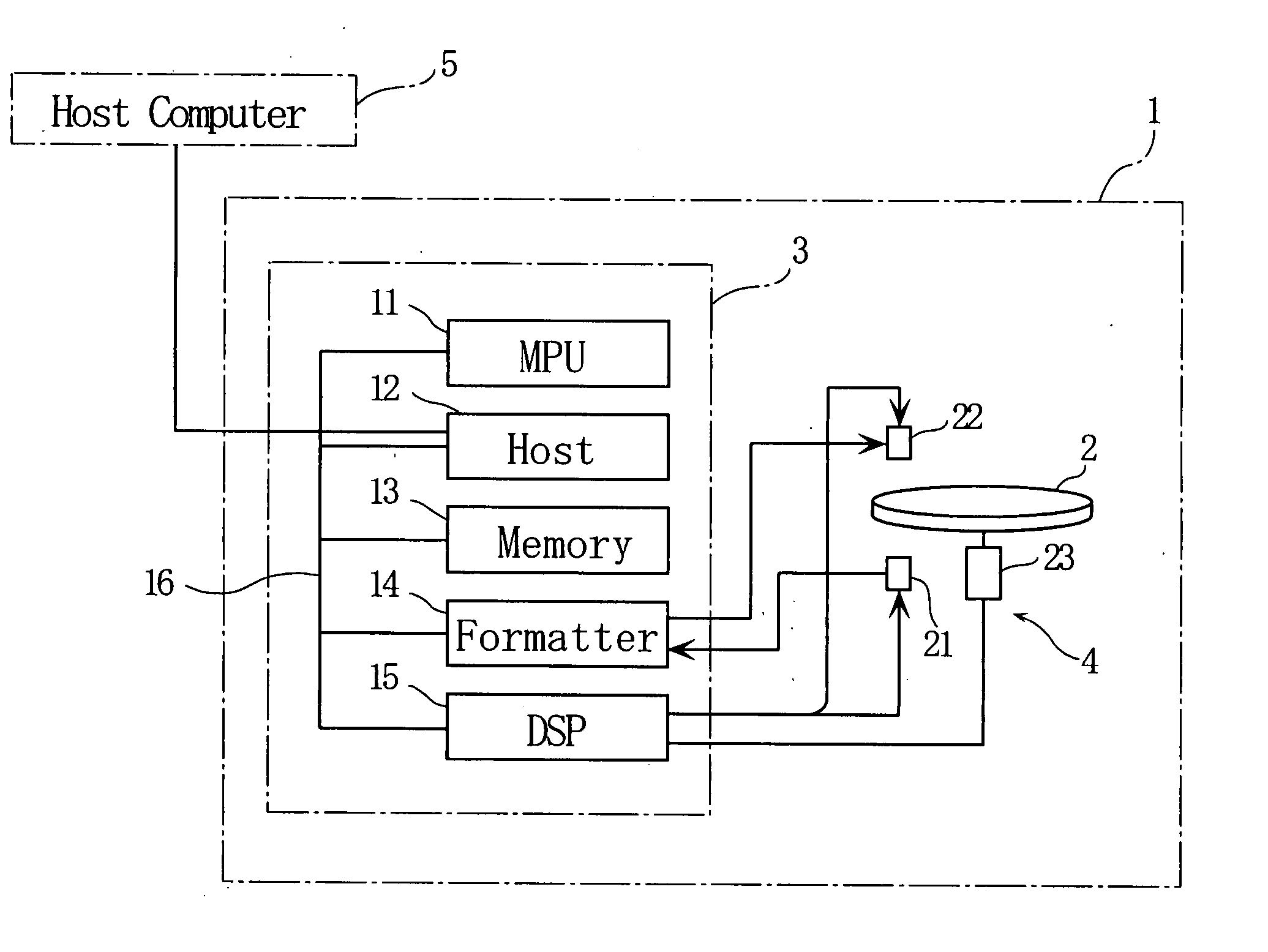
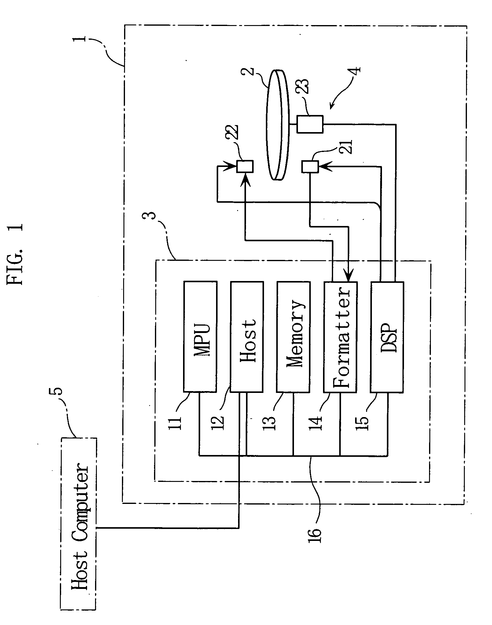
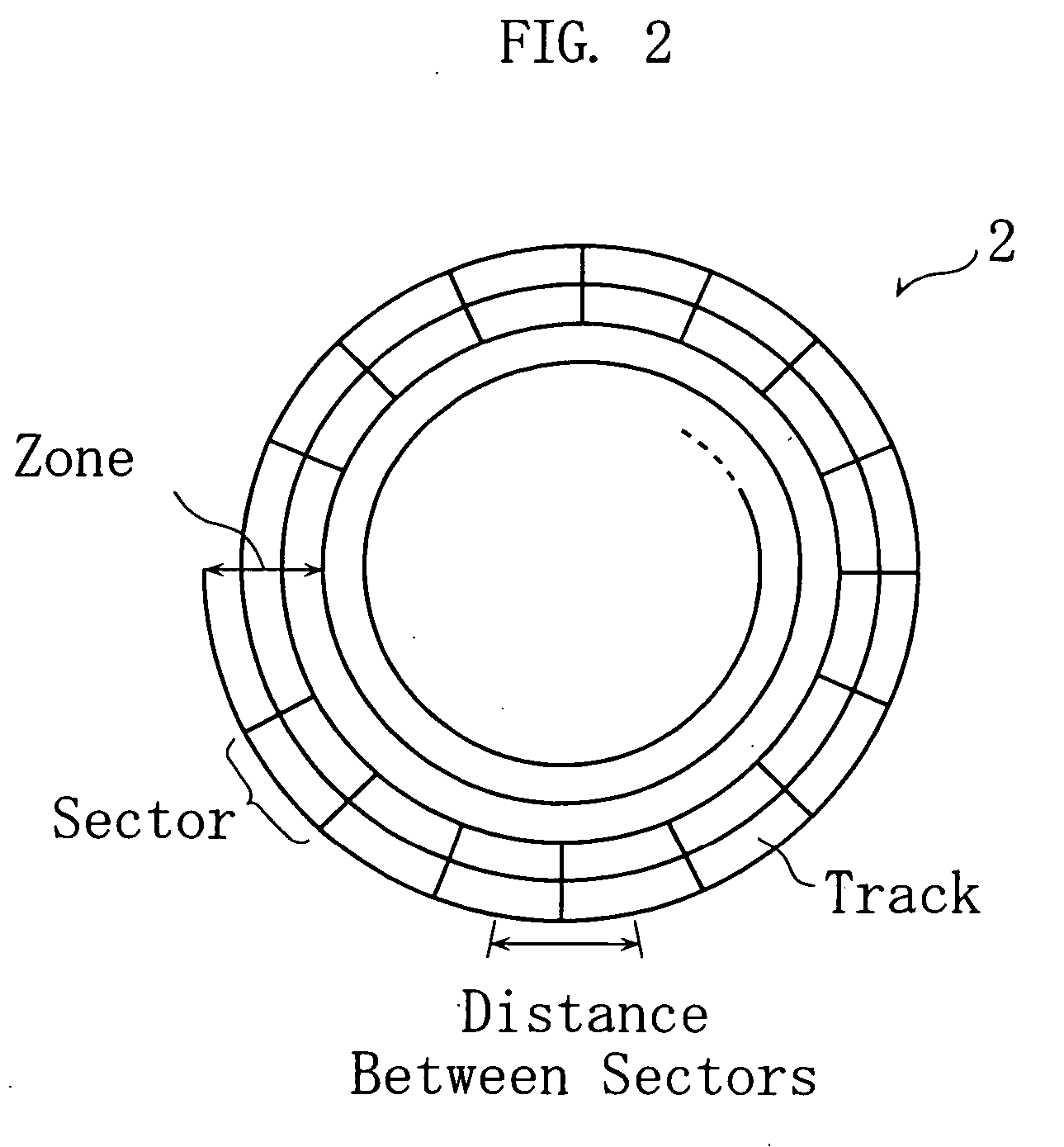
[0061]FIG. 1 an example of the configuration of a magneto-optical disc device to which this invention is applied. FIG. 2 shows an example of tracks formed on a magneto-optical disc.

[0062] This magneto-optical disc device 1 comprises a mountable magneto-optical disc 2, and is used to write data onto a magneto-optical disc 2 or to read data from a magneto-optical disc 2.

[0063] The magneto-optical disc 2 used in this aspect is formatted using the ZCAV (Zoned Constant Angular Velocity) method or the ZCLV (Zoned Constant Linear Velocity) method. Specifically, as shown in FIG. 2, by cutting a spiral-shape guide groove in advance in the surface of the magneto-optical disc 2 proper, a track (land) on which data is recorded is formed in a spiral shape; and this track is divided into a plurality of tracks in units of one disc circumference, and a track number is recorded in advance on each tr...


PUM


Abstract

A magneto-optical disc device (1) writes data, for each sector, onto a magneto-optical disc (2) using an optical head portion (21) which outputs light onto the magneto-optical disc, at which time the data on the magneto-optical disc (2) is erased and after data is erased, data is written onto the magneto-optical disc (2), and the original data is then verified against the written data for each sector. When verifying the original data against the written data, if a verification error is detected for a sector, position information for the sector on the magneto-optical disc (2) in which a verification error is detected is stored in memory (16). Data verification is continued even when a verification error is detected, and at the end of data verification, data verification is again performed for sectors in which verification errors are detected, based on the position information for sectors stored in memory (16).

Description

TECHNICAL FIELD [0001] This invention relates to a magneto-optical disc device which writes data to a magneto-optical disc, and a method of writing data to a magneto-optical disc. BACKGROUND ART [0002] A magneto-optical disc device is a device which writes data to and reads data from a magneto-optical disc (see for example Japanese Patent Laid-open No. 2002-109837). When a magneto-optical disc device is for example connected to a host computer, upon receiving a write command signal and data for writing from the host computer, the device writes data to a magneto-optical disc as recording media in sectors, which are unit recording regions for data. [0003] A sector is specified by a logical block address, which is a logical address on a magneto-optical disc. A write command signal comprises a logical block address, which indicates the starting position for writing, and a number of continuous sectors for writing from the logical block address. [0004] In magneto-optical disc devices, the...

Claims


Application Information

Patent Timeline
IPC IPC(8): G11B11/00G11B7/00G11B7/0045G11B11/105G11B20/18
CPCG11B11/10504G11B11/10595G11B20/18G11B20/1879G11B20/1883G11B2020/1062G11B2020/183G11B2220/20G11B2220/2525
Inventor FUKUNAGA, SYOUJINAKANO, TAKAHIROMARUYAMA, TETSUO
Owner FUJITSU LTD
Learn More