
Flight simulator panel with active graphic display instrumentation

Inactive Publication Date: 2006-07-20
ZORA FAIEK
View PDF7 Cites 20 Cited by
  • Summary
  • Abstract
  • Description
  • Claims
  • Application Information

AI Technical Summary

Benefits of technology

[0011] It is another object to provide an improved flight training device or flight simulator having electronic active graphic display of an aircraft instrument and instrument controls accurately representative in form, function, and tactile feel of the simulated aircraft and accurately spatially oriented as in the actual aircraft, in order to present the pilot with an accurate instrument face image even in a “cross-cockpit” view.

Problems solved by technology

Unfortunately, actual aircraft instruments and simulated aircraft instruments are quite expensive.
However, as computer generated graphic display technology improved and the cost of such technology decreased, it became more cost effective to seek methods for the utilization of electronic active graphic displays of three dimensional, analog instruments.
Unfortunately, in both cases the proximity of the CRT / LCD screen to the instrument face bezel interferes with accurate placement and spatial orientation of the instrument controls.
The resulting pilot view of the simulated instrument panel, particularly in a “cross-cockpit” view, presented the pilot with a less than accurate recessed instrument face image.
On the other hand, any adaptations to the control mechanism to accommodate the CRT / LCD tends to degrade the tactile feel of the instrument controls and detracts from realism.
Any lengthier computational latency can manifest itself as an unrealistic stepping movement of the displayed image.

Method used


Image

  • Flight simulator panel with active graphic display instrumentation
  • Flight simulator panel with active graphic display instrumentation
  • Flight simulator panel with active graphic display instrumentation

Examples


Embodiment Construction

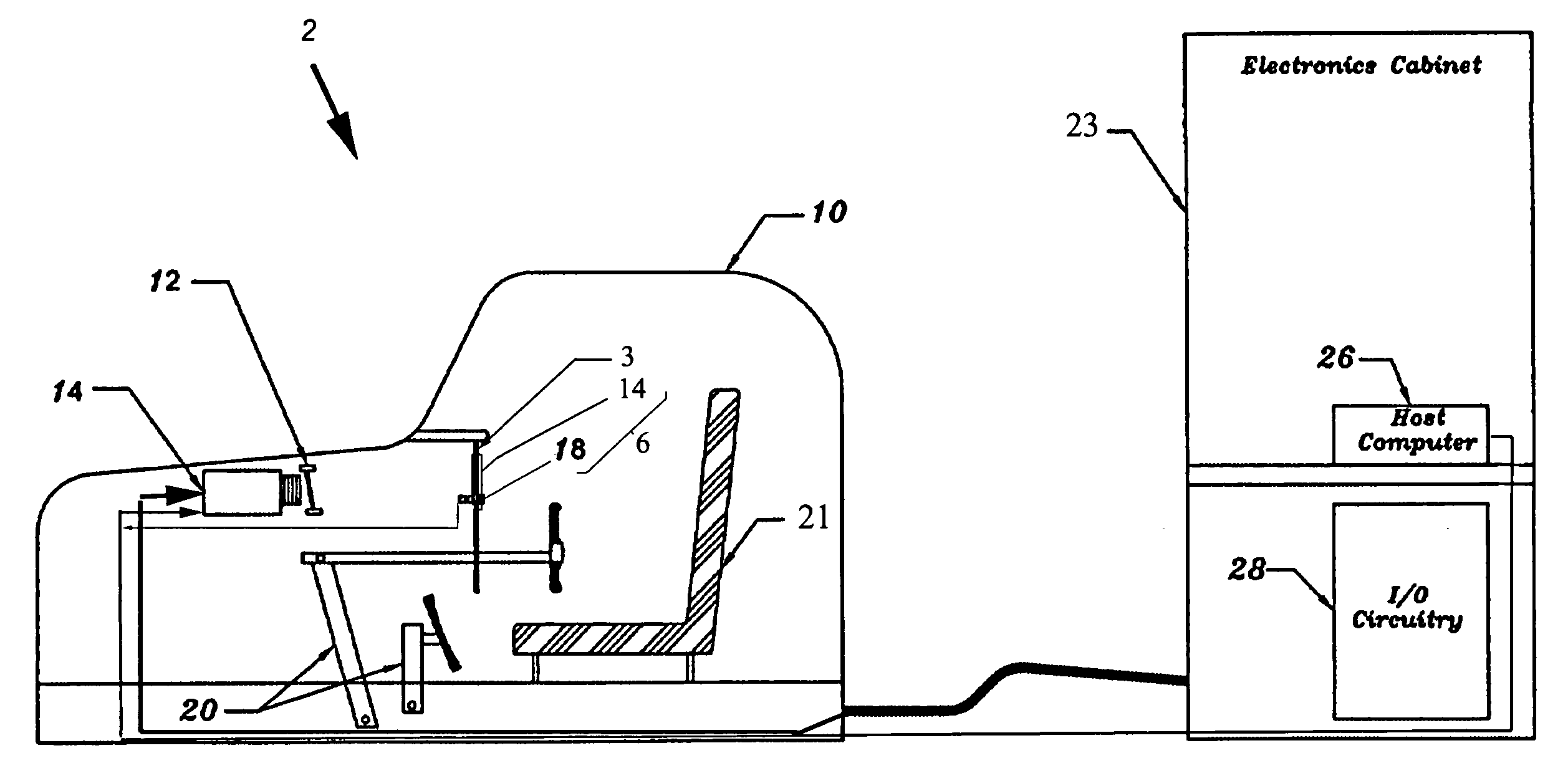
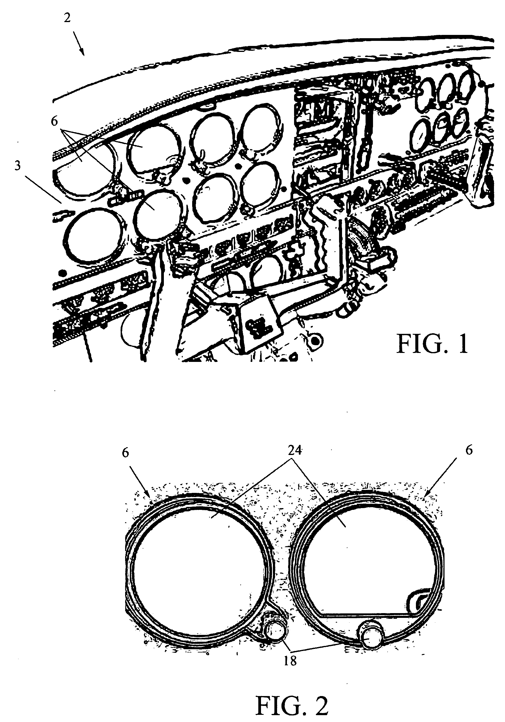
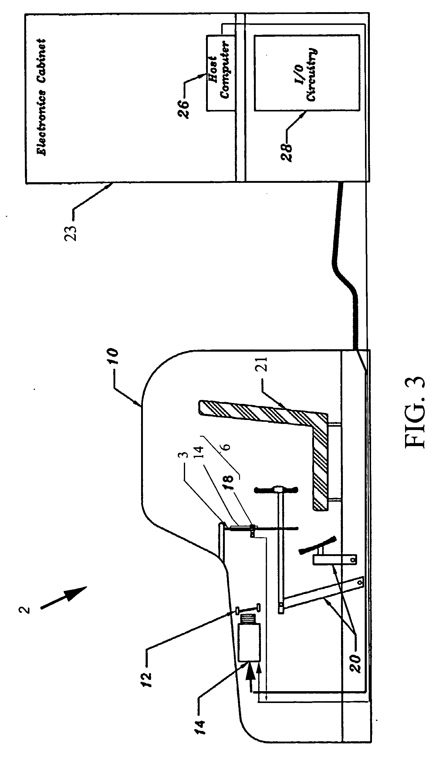
[0026]FIG. 1 is a perspective cross-cockpit view of a flight simulator training device 2 (flight simulator) according to one embodiment of the present invention. The flight simulator 2 includes an instrument console 3 including a plurality of simulated instruments 6 mounted behind a dash.

[0027]FIG. 2 is a front view of two simulated instruments 6 as in FIG. 1. Each simulated instrument 6 includes an electronic active graphic display 24 representing an actual aircraft instrument. Each simulated instrument 16 also includes a rotary electromechanical instrument control device 18, including a knob associated with the active graphic display 24, the knob of control device 18 being constrained by a mechanical static-friction coupling (as will be described) to impart a realistic frictional feel. In a preferred embodiment the aircraft cockpit area includes a full complement of simulated instruments 6, as well as other pilot instrument panels, pilot controls, pilot seats, and other equipment...


PUM


Abstract

A more realistic flight simulator that includes at least one projected electronic active graphic display of an aircraft instrument by means of an LCD projector device, and a rear projection screen material contained within an overlaying bezel which defines the perimeter of the subject simulated aircraft instrument face. The simulated display is controlled by a rotary control inclusive of a rotary switch, a mechanical static fiction device, a mechanical linking shaft and a knob, all mounted to the instrument panel at the bezel. The friction device provides the tactile force feel feedback of the instrument control indicative of the actual aircraft instrument being simulated. The electronic output from the rotary switch is connected to flight training device or flight simulator host computer by electronic input / output circuitry that is utilized to selectively vary the electronic active graphic display of the instrument face through the software graphic driver to the LCD projector.

Description

CROSS-REFERENCE TO RELATED APPLICATIONS [0001] The present application derives priority from U.S. Provisional Application No. 60 / 644,087 filed: Jan. 14, 2005.BACKGROUND OF THE INVENTION [0002] 1. Field of the Invention [0003] The present invention relates to flight simulator instrumentation and, more particularly, to a flight simulator panel that employs projected active graphic display instrumentation. [0004] 2. Description of the Background [0005] The complexity, operating costs, and the operating environment of modem airplanes, together with the technological advances made in flight simulation, have encouraged the uses of simulated flight training devices and flight simulators for training and testing of flight crew members. The instrumentation in a modem airplane may be three dimensional, electromechanical analog aircraft instrumentation, or an electronic flight instrument system (EFIS) displayed on an LCD screen as an active graphic representation of the aircraft information, o...

Claims


Application Information

Patent Timeline
IPC IPC(8): G09B9/02
CPCG09B9/28
Inventor ZORA, FAIEK
Owner ZORA FAIEK
Learn More