Ring-shaped valve prosthesis attachment device

a prosthesis and ring-shaped technology, applied in the field of applicator and method of prosthesis attachment, can solve the problems of affecting the proper movement of the valve leaflet, heart failure, etc., and achieve the effect of reducing fluid leakag

Inactive Publication Date: 2006-07-20
REALYVASQUEZ FIDEL +2
View PDF0 Cites 472 Cited by
  • Summary
  • Abstract
  • Description
  • Claims
  • Application Information

AI Technical Summary

Benefits of technology

[0016] The fasteners may have a curved distal portion. The fasteners may have a sharpened distal tip. The fasteners have a blunt distal tip. They may be made of stainless steel. The fasteners in the first position may extend in part towards the inner circumference of the ring. The fasteners may have a first portion that is straight and a sec

Problems solved by technology

Obviously, if this insufficiency is not corrected, the added workload can eventually result in heart failure.
This involves calcium buildup in the valve which impedes proper valve le

Method used


Image

  • Ring-shaped valve prosthesis attachment device
  • Ring-shaped valve prosthesis attachment device
  • Ring-shaped valve prosthesis attachment device

Examples


Embodiment Construction

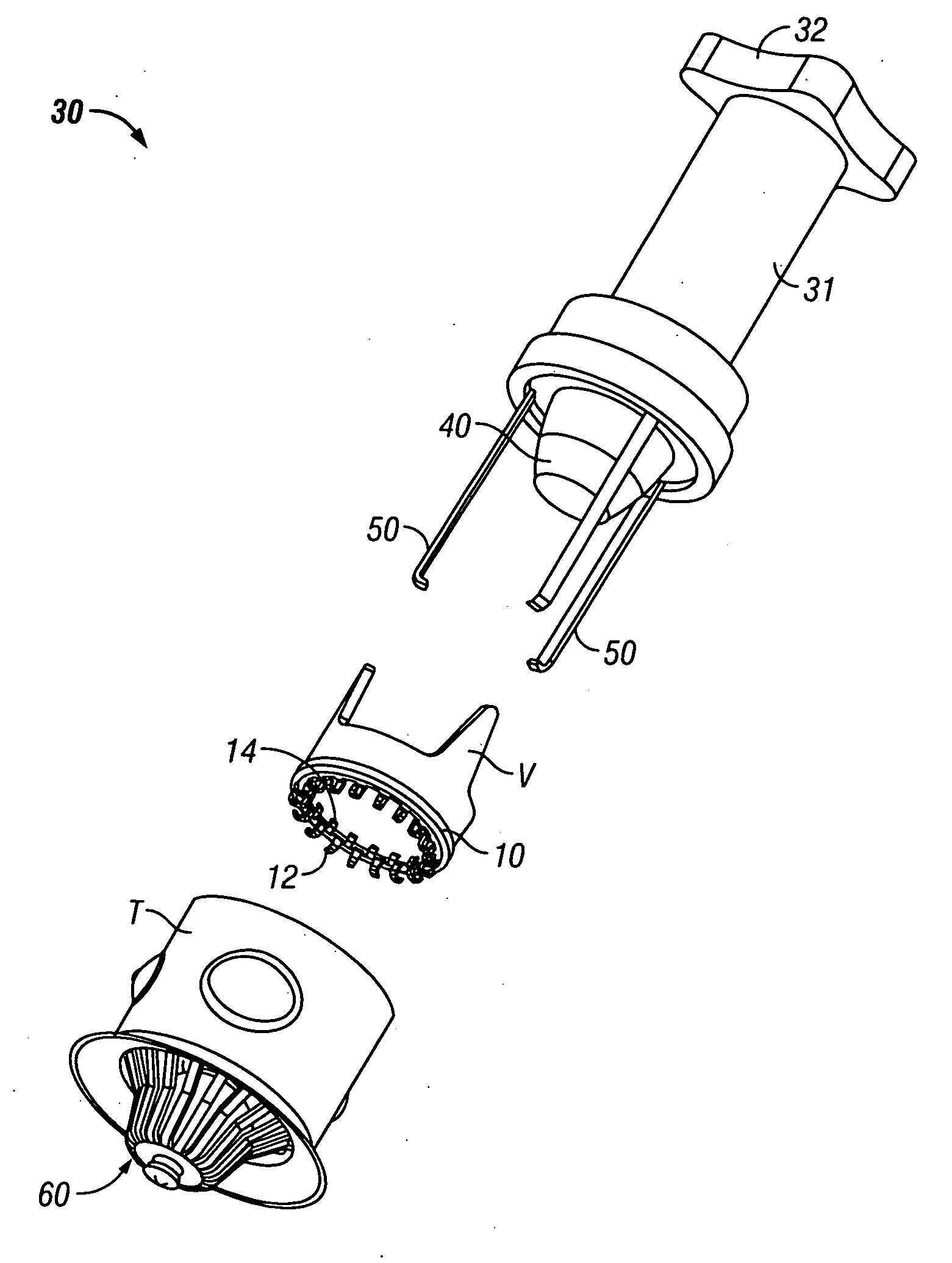
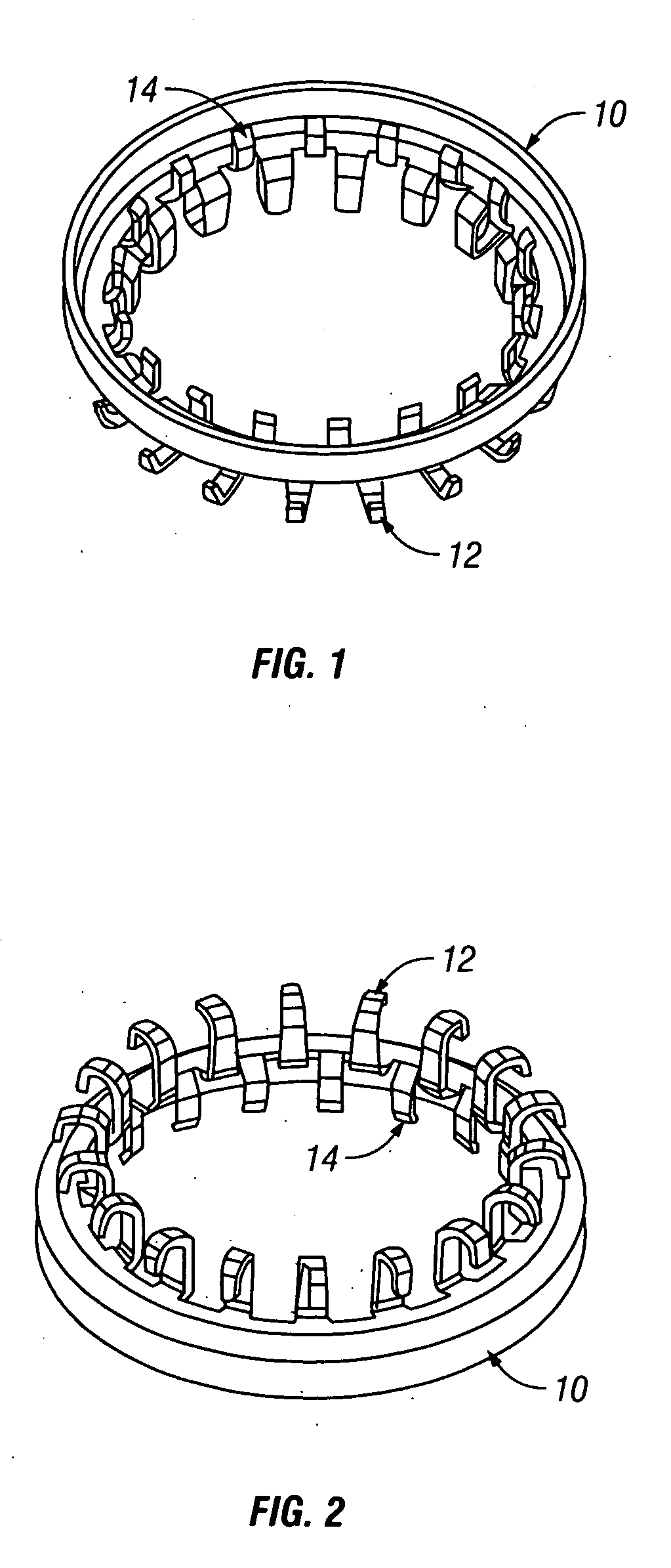
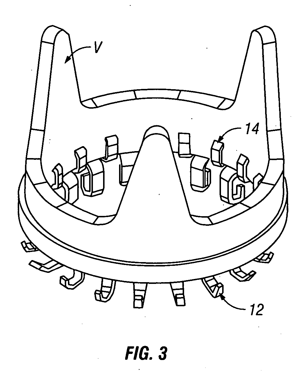
[0025]FIGS. 1 through 3 show one embodiment of a ring according to the present invention.

[0026]FIG. 4 through 5 are views of a ring and a valve prosthesis secured in place.

[0027]FIGS. 6 and 7 show a delivery device.

[0028]FIGS. 8 and 9 show fasteners on a ring FIGS. 10 through 12 show one method of deploying fasteners according to the present invention.

[0029]FIGS. 13 and 14 show side views of one embodiment of the invention.

[0030]FIGS. 15 through 17 show perspective views of the present invention.

[0031]FIGS. 18 and 19 are views of a ring and a valve prosthesis secured in place.

[0032]FIGS. 20 through 24 show one embodiment of a delivery device according to the present invention.

[0033]FIGS. 25 through 27 are views of a ring and a valve prosthesis secured in place.

[0034]FIGS. 28 through 33 show various embodiments of rings according to the present invention.

[0035]FIGS. 34 through 36 show a contoured ring.

[0036]FIGS. 37 through 38 show a ring coupled to a valve.

[0037]FIGS. 39...


PUM


Abstract

A valve delivery device and method of use is provided. In one embodiment, a method for attaching a valve prosthesis to a target tissue includes providing a ring having a portion defining a groove and a plurality of fasteners coupled to the ring. A portion of the valve prosthesis is placed in the groove on the ring. The valve prosthesis portion in the groove is then secured to the ring. The ring is mounted on a delivery device and the delivery device is positioned so that the fasteners will engage the target tissue when the fasteners are deployed. A shaped plunger member may then deployed through an interior of the ring to swing said fasteners from a first position to a second tissue engagement position.

Description

[0001] The present application claims the benefit of priority from U.S. Provisional Application 60 / 629,984 and 60 / 709,185 which are fully incorporated herein for all purposes.BACKGROUND OF THE INVENTION [0002] 1. Technical Field [0003] The invention relates to apparatus and methods for prosthesis attachment and is especially useful in valve repair procedures. [0004] 2. Background Art [0005] Essential to normal heart function are four heart valves, which allow blood to pass through the four chambers of the heart in one direction. The valves have either two or three cusps, flaps, or leaflets, which comprise fibrous tissue that attaches to the walls of the heart. The cusps open when the blood flow is flowing correctly and then close to form a tight seal to prevent backflow. [0006] The four chambers are known as the right and left atria (upper chambers) and right and left ventricles (lower chambers). The four valves that control blood flow are known as the tricuspid, mitral, pulmonary, ...

Claims


Application Information

Patent Timeline
IPC IPC(8): A61F2/24
CPCA61F2/2409A61F2/2427
Inventor REALYVASQUEZ, FIDELMOORE, ROBBABRAMSON, JEFF
Owner REALYVASQUEZ FIDEL
Why Eureka
Try Eureka