Interlocking Corner Joint

a corner joint and interlocking technology, applied in the field of furniture manufacturing, can solve the problems of high price of drawer box joints with mechanical plates, easy failure of most high cost of drawer box joints without mechanical plates, so as to increase the gluing surface area and strength.

Inactive Publication Date: 2006-07-27
SCHULTZ RICHARD THOMAS
View PDF0 Cites 16 Cited by
  • Summary
  • Abstract
  • Description
  • Claims
  • Application Information

AI Technical Summary

Benefits of technology

[0006] The present invention overcomes the disadvantages and limitations of previous solutions by providing a system and method for designing and manufacturing drawer box joints with improved strength and reliability under mechanical stress over time by dramatically increasing the glued surface area of the overlapping pieces of the drawer box joint, and fastening the pieces through multiple steps that prevent the movement of the joint in any of the three x,y,z dimensions in the event of a glue joint failure without the use of additional expensive mechanical plates.
[0009] The advantages of the present invention are that it has an increased gluing surface area resulting in a much higher strength joint and results in a joint that will not fail in any one dimension of the x,y,z plane. Additional metal plates are not needed to achieve the final joint strength. In some cases the resulting joint will not have to be clamped during the cure time of the glue due to its construction.

Problems solved by technology

Drawer box joints with mechanical plates are much more expensive than drawers box joints without mechanical plates.
Most drawer box joints without mechanical plates are susceptible to failure in at least one or more of three possible x,y,z dimensions due to mechanical stress over time.

Method used


Image

  • Interlocking Corner Joint
  • Interlocking Corner Joint
  • Interlocking Corner Joint

Examples


embodiment 200

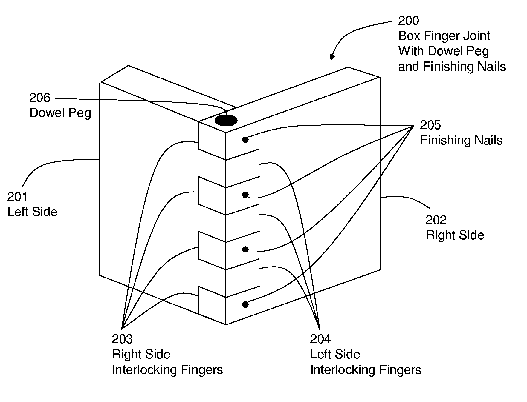
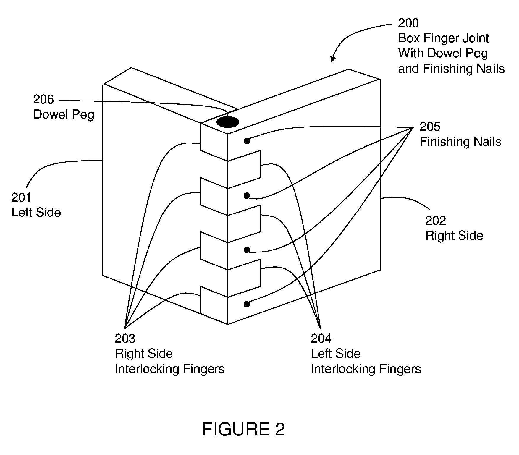
[0023]FIG. 2 illustrates an embodiment 200 of the present invention showing stronger box finger joint with dowel peg and finishing nails. The left side 201 of the box finger joint 200 is created by cutting or forming the alternating left side interlocking fingers 204. In a similar manner, the right side 202 of the box finger joint 200 is created by cutting or forming the alternating right side interlocking fingers 203. Subsequently the left side 201 and right side 202 are joined together and the interface between the right side interlocking fingers 203 and left side interlocking fingers 204, and are typically clamped in a clamping device. While still in the clamping device, a round hole is drilled at the top corner of 200. The pieces can now be removed from the clamping device. Glue is placed in the drilled hole and at the interface of the right and left side interlocking fingers 203 and 204 respectively. The pieces are clamped in a clamping device and subsequently a dowel peg 206 i...

embodiment 300

[0024]FIG. 3 is an illustration of an embodiment 300 of a left side cross section of the corner of the box finger joint with dowel peg and finishing nails 200 in FIG. 2. The left side 301 is aligned so that the left side interlocking fingers 304 are perpendicular to the right side interlocking fingers 303. The hole is drilled at the corner of 300 through the left and right side interlocking fingers 304 and 303 respectively. The location of the dowel peg 306 inserted into the hole and through 303 and 304 is shown. The finishing nails 305 may be driven into the right side interlocking fingers 303 and through the dowel peg 306 and into the left side 301.

embodiment 400

[0025]FIG. 4 is an illustration of an embodiment 400 of a right side cross section of the corner of the box finger joint with dowel peg and finishing nails 200 in FIG. 2. The right side 402 is aligned so that the right side interlocking fingers 403 are perpendicular to the left side interlocking fingers 404. The hole is drilled at the corner of 400 through the right and left side interlocking fingers 403 and 404 respectively. The location of the dowel peg 406 inserted into the hole and through 403 and 404 is shown. The finishing nails 405 may be driven into the right side interlocking fingers 403 and through the dowel peg 406 and into the left side.


PUM


Abstract

A method of constructing an interlocking corner joint by combining fixed or variable sized interlocking fingers from at least two sides, full or partial feed though dowel pegs or other geometrically shaped pegs, finishing nails, pins or screws and glue or epoxy at the interface of the interlocking fingers and pegs and pins. The resulting interlocking corner joint is much stronger than a standard dovetail joint or box finger joint due to the increased surface area created by the holes, pegs and pins. Due to the interlocking fingers, holes, pegs and pins, the interlocking corner joint will not pull apart in any one dimension x,y,z in the event that the glue joint fails.

Description

FIELD OF THE INVENTION [0001] The present invention pertains generally to furniture manufacturing and specifically but is not limited to the making of drawer box joints. BACKGROUND OF THE INVENTION [0002] Drawer box joints are generally made several ways from wood of varying species or composite woods and vary from manufacturer to manufacturer. Drawer box joints generally are made from finger box joints, dovetail joints, lap joints, tongue and groove joints and other similar joints. [0003] Drawer box joints are typically fastened together with some type of wood glue or epoxy and where the glue or epoxy is applied directly at the interface between the pieces of wood that overlap. In some cases mechanical plates are applied in addition to the glue joints. This added mechanical fastener provides additional strength to the joint and makes the joint less susceptible to mechanical stress over time. Drawer box joints with mechanical plates are much more expensive than drawers box joints wi...

Claims


Application Information

Patent Timeline
Patent Type & Authority Applications(United States)
IPC IPC(8): E04B1/00E04G21/00
CPCF16B12/125
Inventor SCHULTZ, RICHARD THOMAS
Owner SCHULTZ RICHARD THOMAS
Why Eureka
Try Eureka