Dynamic damper and manufacturing method therefor

A shock absorber and ring technology, applied in the direction of the casing/cover/support, electrical components, electromechanical devices, etc., can solve the problem of difficulty in increasing the bonding surface area, so as to increase the bonding surface area and simplify production. method, the effect of reducing production costs

Inactive Publication Date: 2011-08-10
SHINANO KENSHI +1
View PDF1 Cites 0 Cited by
  • Summary
  • Abstract
  • Description
  • Claims
  • Application Information

AI Technical Summary

Problems solved by technology

Therefore, it is difficult to increase the bonding surface area, which will be bonded to the bonding surface of the rubber piece
[0008] In addition, if the hub is made of sintered material, oil and machining oil included in the metal powder used for bonding will tend to remain in the hub, making it difficult to vulcanize the hub with high bonding force bonded to rubber parts

Method used

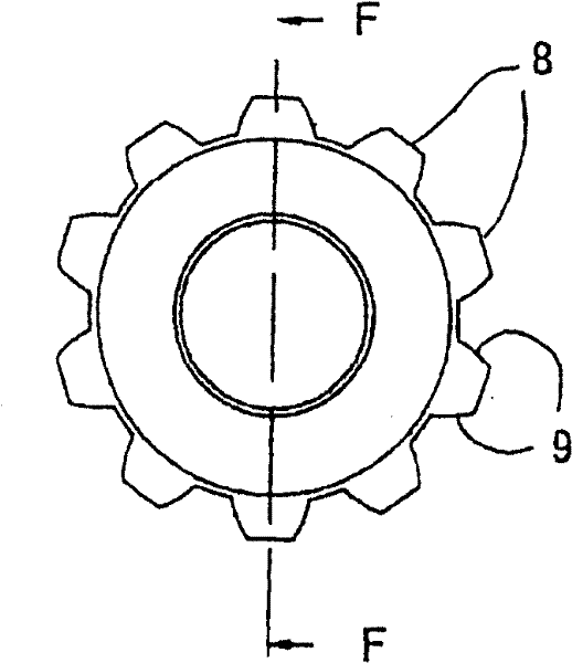
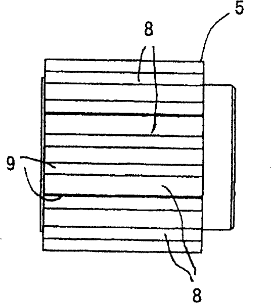
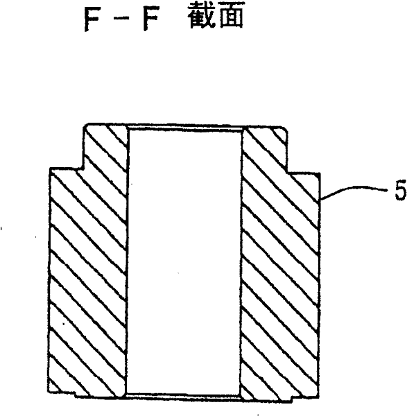

Image

  • Dynamic damper and manufacturing method therefor
  • Dynamic damper and manufacturing method therefor
  • Dynamic damper and manufacturing method therefor

Examples


Embodiment Construction

[0042] Preferred embodiments of the present invention will now be described in detail with reference to the accompanying drawings.

[0043] The shock absorber of the present invention is mainly press-fitted on the rotating shaft of the motor and used to absorb vibration.

[0044] In the following embodiments, an inner rotor type stepping motor used, for example, to drive a scanner of a copier, to drive a carriage of a printer, or to drive a sheet feeder of a printer is explained as an example of a motor.

[0045] The shape of the stepping motor will refer to the figure 1 to explain.

[0046] exist figure 1 In , the rotor includes a rotor core having rotor teeth, and the rotor rotates together with a rotating shaft 1 made of a non-magnetic material. The stator includes a stator core surrounding the rotor. The stator core comprises magnetic poles which in turn have stator toothing facing the rotor toothing of the rotor core. The excitation wire is wrapped around the pole wi...


PUM


Abstract

The environment-friendly dampers at low cost which can be manufactured by simplify method and facilitate achievement of dimension accuracy. The dynamic damper includes a press-fitting part fitted with a rotation shaft of motor. The press-fitting part includes: a first annular member made of sintered material; a second annular disposed on the outside of the first annular member for generating inertia mass; and a vibration isolating member fixed on the first annular member and the second annular member in the axial direction.

Description

technical field [0001] The present invention relates to a shock absorber press-fitted to the rotating shaft of an electric motor and a method of manufacturing the shock absorber Background technique [0002] A fixed frame type motor is disclosed in Japanese Patent Publication No. 2004-28295 as an example of the motor. In this motor, a rotating shaft connected to the motor is rotatably supported by a pair of brackets with bearings. A shock absorber arrangement is provided at one end of the rotating shaft, which is located on the opposite side of the output side to prevent vibration of the motor, limit or dampen its speed fluctuations and calm it. The shock absorber has: a cylindrical hub, which is press-fitted on the rotating shaft; an inertia plate, which is coaxially arranged on the outside of the hub to impart inertial mass to the motor; and an anti-vibration rubber member, which is bonded to the hub and the inertia plate. [0003] If the shock absorber is press-fitted ...

Claims


Application Information

Patent Timeline
Patent Type & Authority Patents(China)
IPC IPC(8): H02K5/24H02K37/24
Inventor 铃木丰佐藤英信岩渊宣郎
Owner SHINANO KENSHI
Why Eureka
Try Eureka