Chip-based CPU cooler and cooling method thereof

Inactive Publication Date: 2006-07-27
ITER NETWORKING CORP
View PDF3 Cites 28 Cited by
  • Summary
  • Abstract
  • Description
  • Claims
  • Application Information

AI Technical Summary

Benefits of technology

[0006] It is therefore an object of the present invention to provide a chip-based CPU cooling device having a metal cov

Problems solved by technology

Heat dissipation thus has become a critical issue in maintaining the normal operation of a CPU (i.e., computer).
However, the desired good heat dissipation of CPU is compromised as interference among heat conduction, convection, and r

Method used


Image

  • Chip-based CPU cooler and cooling method thereof
  • Chip-based CPU cooler and cooling method thereof
  • Chip-based CPU cooler and cooling method thereof

Examples


Embodiment Construction

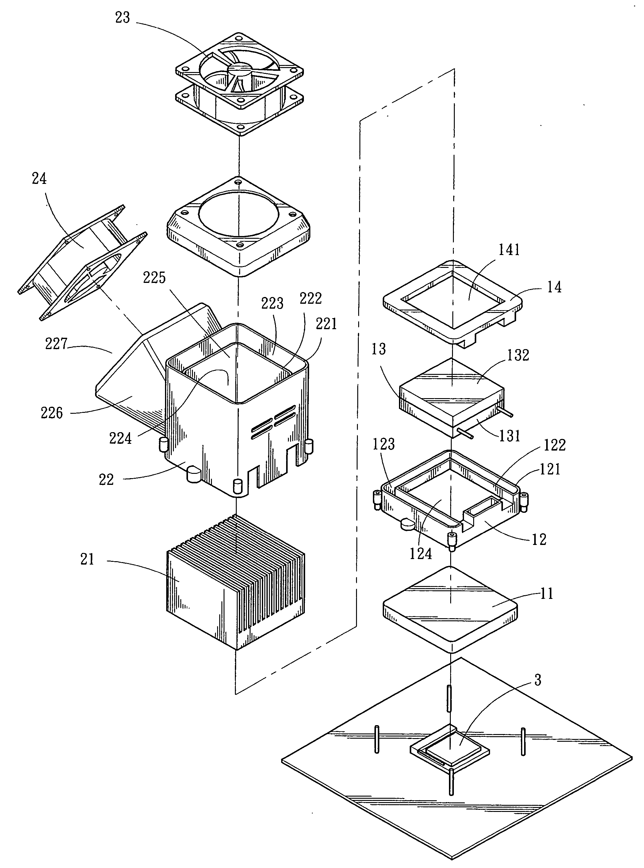
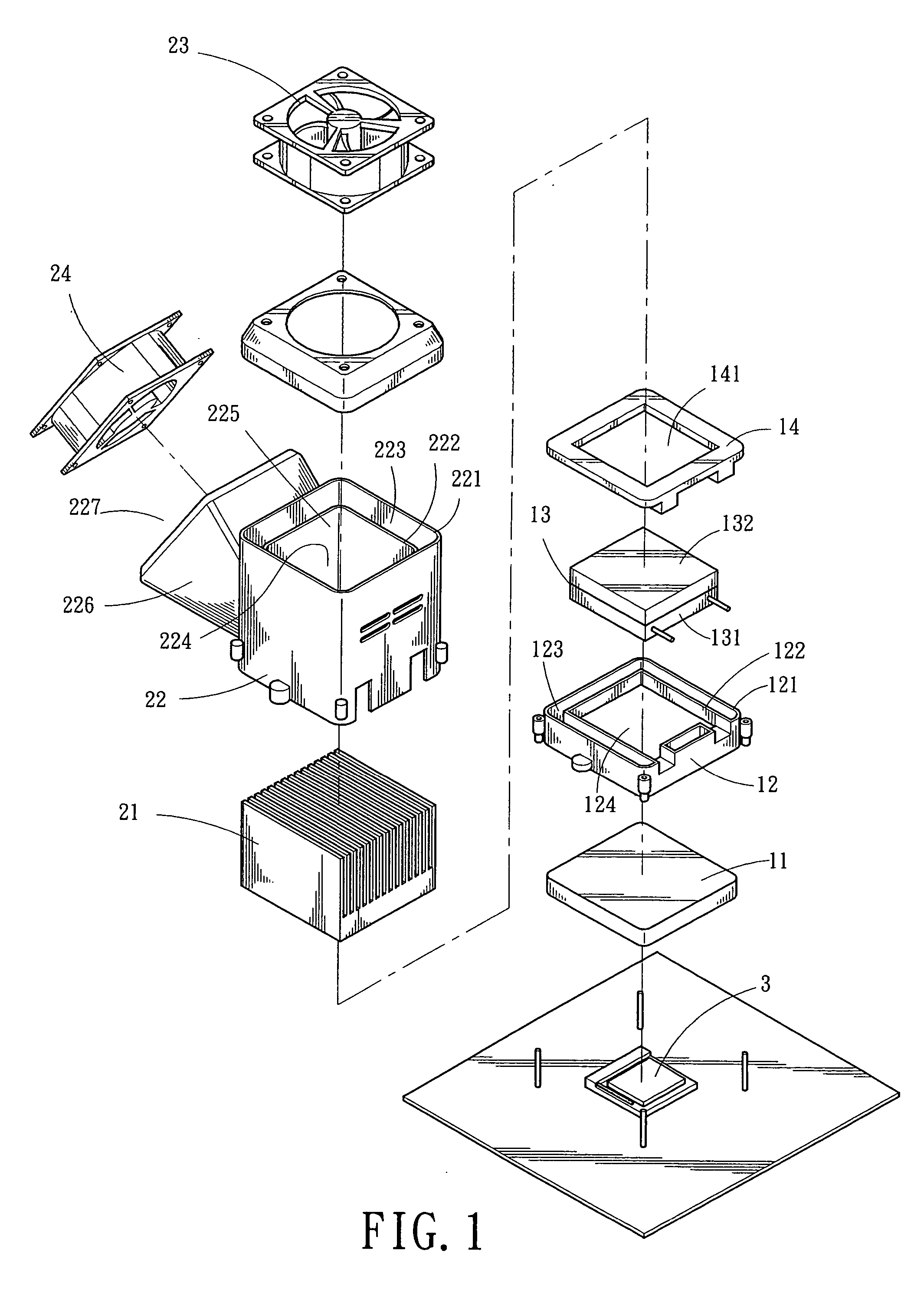
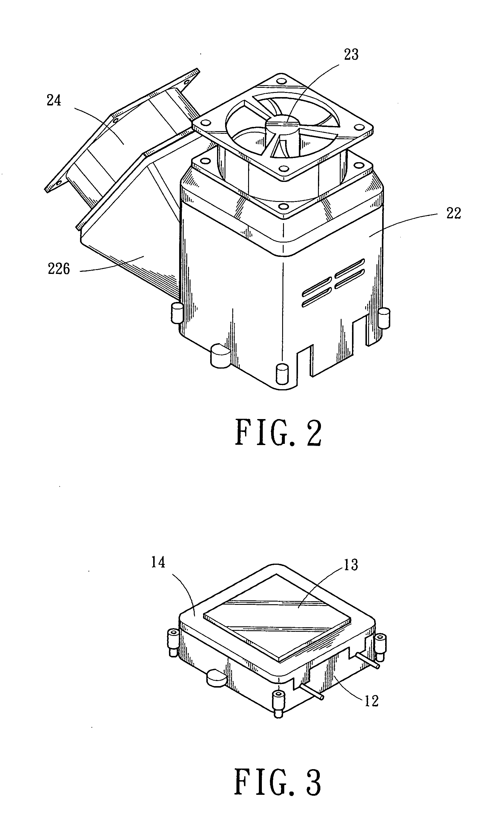
[0018] Referring to FIGS. 1 to 4, there is shown a cooling device for CPU in accordance with a preferred embodiment of the invention. The cooling device comprises a cover 11 formed of metal of high heat conductivity, a seat 12, a thermal electric cooler 13, a frame 14, a plurality of fins 21 of high heat conductivity as a heat sink, a housing 22, a first fan 23, and a second fan 24. Each component is discussed in detailed below.

[0019] A CPU 3 is completely covered by the cover 11 thereon. The cover 11 also completely contacts the CPU 3 and the thermal electric cooler 13. The cover 11 is served to direct out heat produced from CPU 3. The square hollow seat 12 comprises an outer U-shaped wall 121, an inner U-shaped wall 122, a U-shaped groove 123 defined by the walls 121 and 122 for directing air communication with the cover 11 (i.e., no external air interference), and a central opening 124 which is a hollow-through opening. A chip powered by flowing electric current therethrough is ...


PUM


Abstract

Provided are chip-based CPU cooling device and cooling method thereof. The cooling device comprises a metal cover adapted to completely cover and contact the CPU, a hollow seat, a thermal electric cooler shaped to fit in the seat and adapted to contact the cover, a heat dissipation member (e.g., fins) enclosed by a housing and mounted on the seat for contacting the thermal electric cooler, a first fan mounted on top of the housing, and a second fan mounted on side of the housing. An optimum heat dissipation can be obtained by running a control program to control on/off of the fans and power of the thermal electric cooler by operating the cooling device in one of a plurality of corresponding temperature ranges of the CPU.

Description

BACKGROUND OF THE INVENTION [0001] 1. Field of Invention The present invention generally relates to CPU (central processing unit) cooling devices and more particularly to a chip-based CPU cooling device having a thermal electric cooler and a cooling method thereof. [0002] 2. Description of Related Art [0003] Operating frequency of the CPU of a computer has been continuously increasing as the technology develops. Accordingly, heat generated by a running CPU increases greatly. Heat dissipation thus has become a critical issue in maintaining the normal operation of a CPU (i.e., computer). [0004] Conventionally, a CPU cooler is implemented as a passive one. In detail, a member formed of high heat conduction metal or alloy is mounted on the CPU. The member comprises a plurality of parallel fins. In operation, heat generated by CPU is transferred to the fins by contact prior to dissipating to the ambient. For achieving maximum heat dissipation, the number of fins, locations of the fins, a...

Claims


Application Information

Patent Timeline
IPC IPC(8): F25B21/02F25D23/12
CPCG06F1/20G06F1/206H01L23/467H01L2924/0002H01L2924/00
Inventor KUO, WEI-CHEN
Owner ITER NETWORKING CORP
Why Eureka
Try Eureka