Switching controlling apparatus

a technology of switching control and control apparatus, which is applied in the direction of mechanical apparatus, control system, dynamo-electric converter control, etc., can solve the problems of time elapse after the stop of energizing the electrically operated actuator, difficulty in bringing the mechanical “detent stabilizing position, and difficulty in predicting individual variations, etc., to achieve the effect of restoring spring force, shortening the time elapsed, and restoring torqu

Inactive Publication Date: 2006-07-27
DENSO CORP
View PDF4 Cites 22 Cited by
  • Summary
  • Abstract
  • Description
  • Claims
  • Application Information

AI Technical Summary

Benefits of technology

[0016] With this, the output torque of the electrically operated actuator is reduced before energizing the electrically operated actuator is stopped and hence even when “the drive / control stopping position” deviates from “a detent stabilizing position,” an abrupt change does not occur in the balance between “drive / control stopping torque” and “restoring spring force.” For this reason, it is possible to prevent a malfunction that the first member (for example, a detent plate and the like) is swung by the action of inertia moment and restoring spring force.
[0017] In this manner, even when “the drive / control stopping position” deviates from “a detent stabilizing position,” the first member is prevented from being swung after energizing the electrically operated actuator is stopped. Therefore, it is possible to shorten the time that elapses after energizing the electrically operated actuator is stopped until the first member stops.
[0018] Moreover, it is possible to eliminate a malfunction caused by a phenomenon that the first member swings (for example, a malfunction that when the detent plate swings, the manual spool valve also swings to change the area of an oil passage switched by the manual spool valve).

Problems solved by technology

However, mechanical parts constructing the shift-range-switching apparatus have individual variations caused in a manufacturing process and the like and hence it is difficult to bring the mechanical “detent stabilizing position” and the electrical “drive / control stopping position” into perfect agreement.
Moreover, it is also difficult to predict individual variations and to provide electric motor control with a control constant for canceling the variations.
For this reason, there is presented a problem that the time elapsing after energizing the electrically operated actuator is stopped until the detent plate stops at “the detent stabilizing position” becomes long.
When the manual spool valve swings in a hydraulic valve body, the area of an oil passage switched by the manual spool valve changes to cause a delay in the switching of an automatic transmission and the like.

Method used


Image

  • Switching controlling apparatus
  • Switching controlling apparatus
  • Switching controlling apparatus

Examples


first embodiment

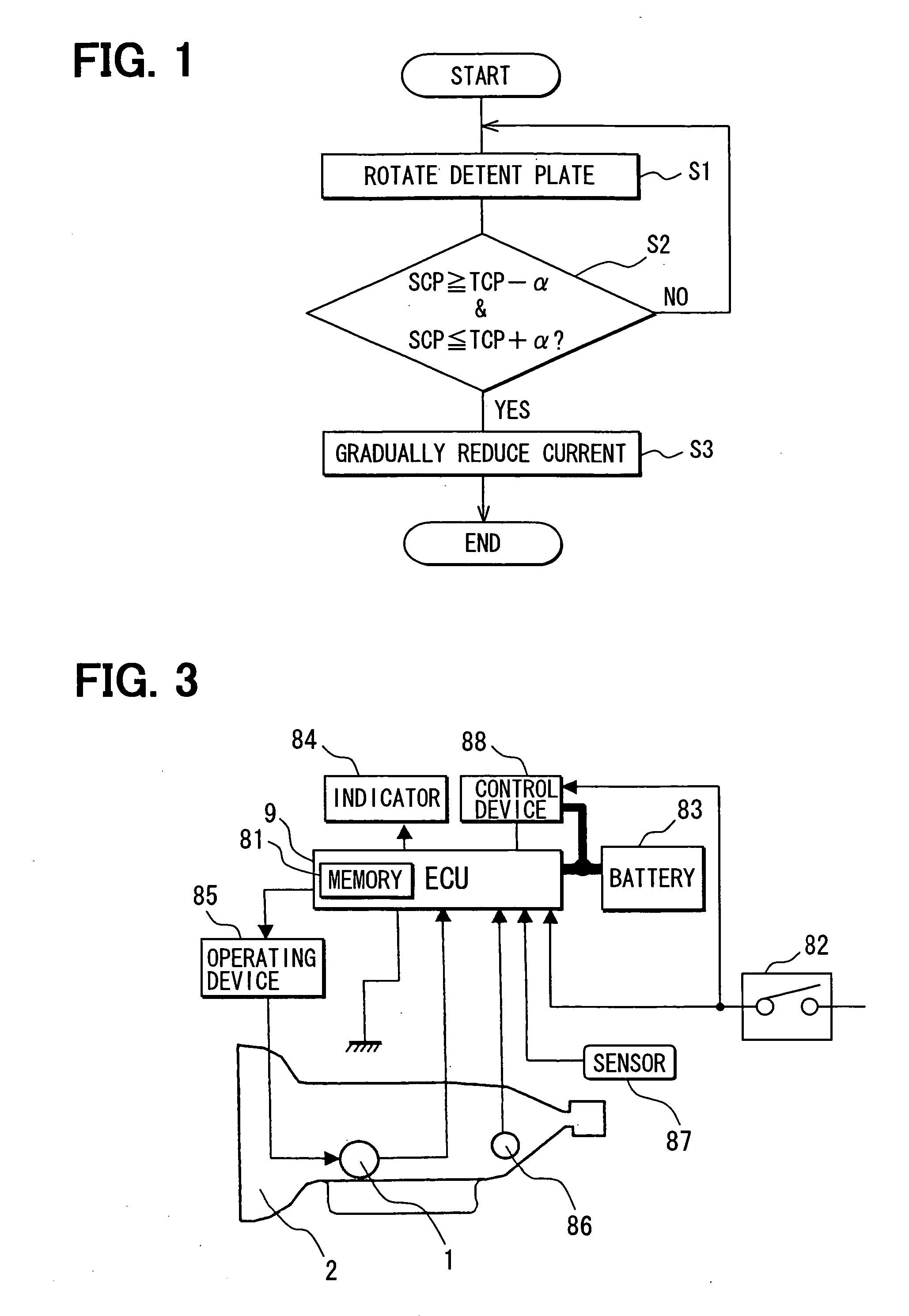
[0044] First embodiment will be described with reference to FIG. 1 to FIGS. 20A and 20B.

[0045] In first embodiment, the present invention is applied to a shift-range-switching device of an automatic transmission for a vehicle. First, a shift-range-switching device will be described.

(Description of Shift Range Changing Device)

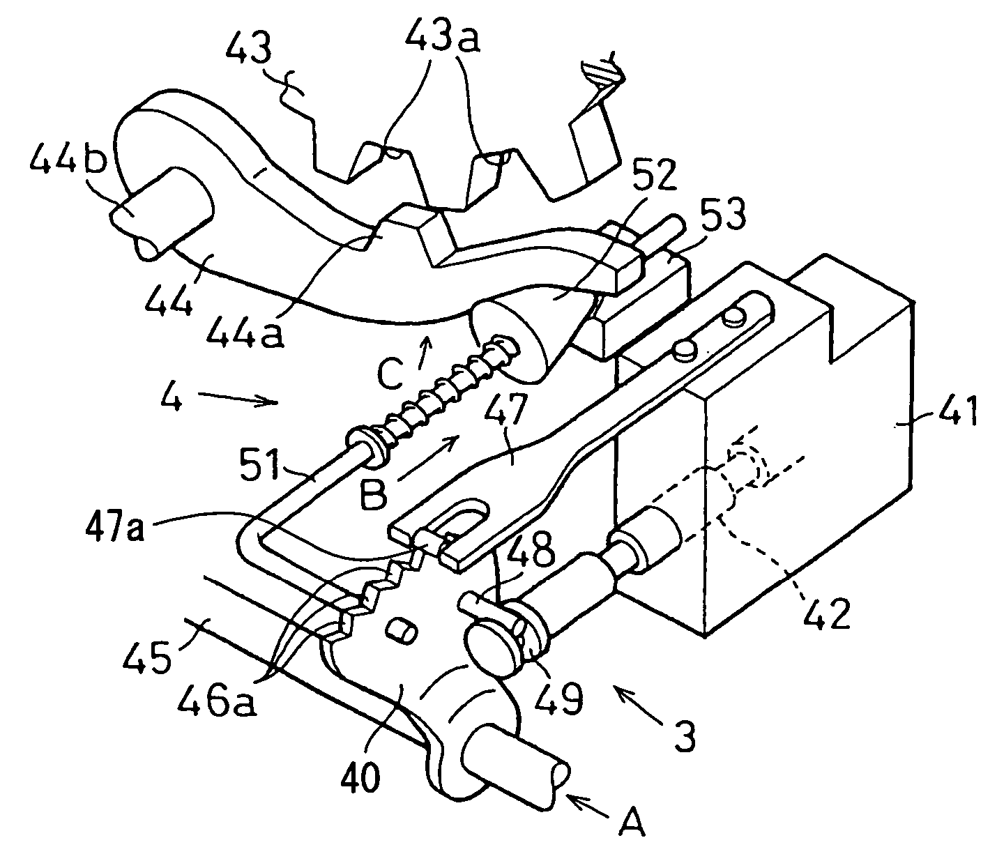
[0046] The shift-range-switching device switches a shift-range-switching mechanism 3 (including a parking switching mechanism 4: refer to FIG. 4) mounted on an automatic transmission 2 for a vehicle (refer to FIG. 3) by an electrically operated actuator 1 (refer to FIG. 2) developing a rotational output.

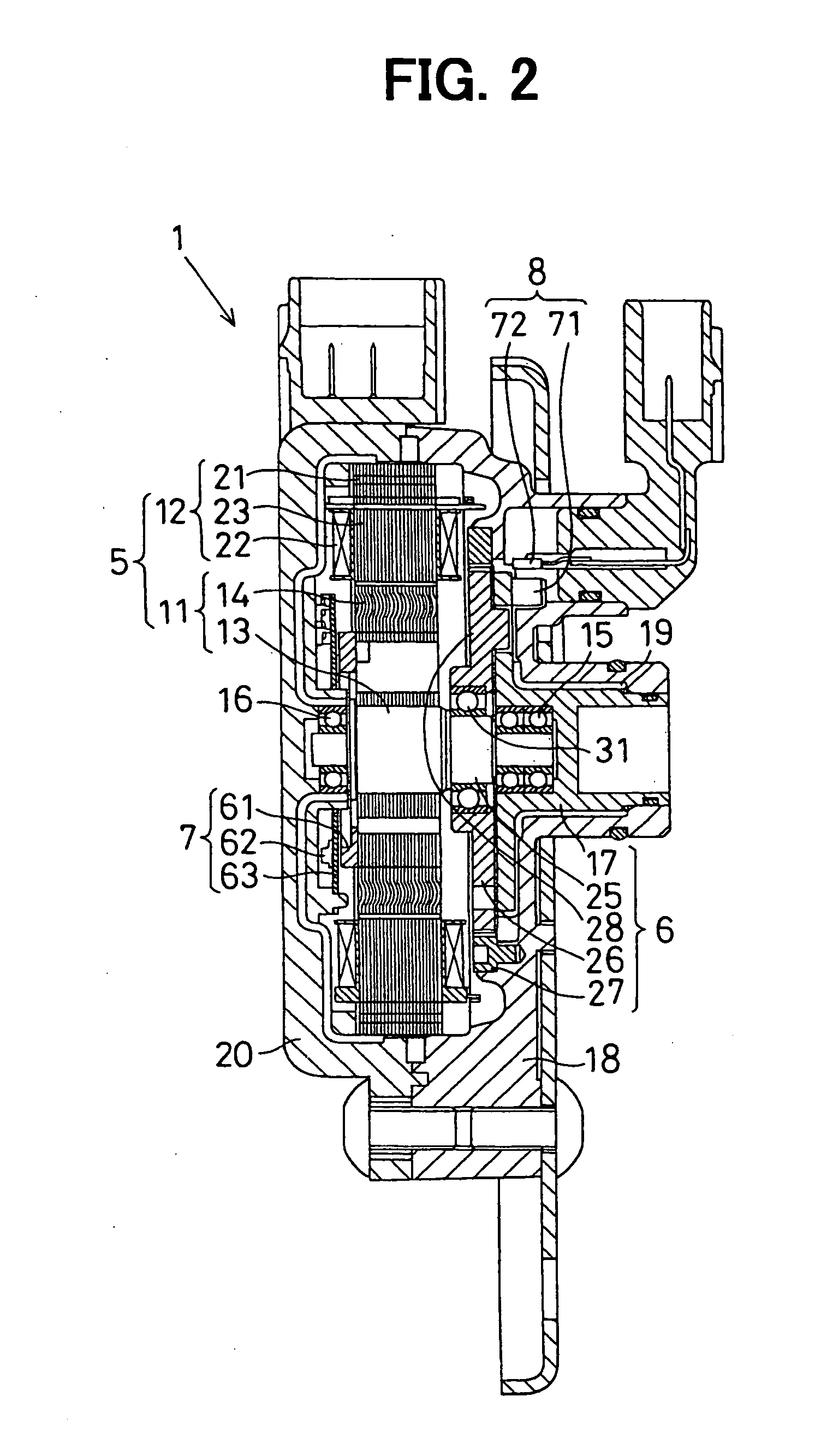
[0047] The electrically operated actuator 1 is a servo mechanism for driving the shift-range-switching mechanism 3 and includes a synchronous electric motor 5, a reduction gear 6 for reducing the rotational output of this electric motor 5 to drive the shift-range-switching mechanism 3, an encoder 7 for detecting the rotational angle of the electric motor 5, ...

second embodiment

[0151] Second embodiment will be described with reference to FIG. 21. Here, parts shown by the same reference symbols in the following embodiment as in first embodiment denote the same functioning parts.

[0152] When the detent plate 46 reaches “the drive / control stopping position” and then energizing the electrically operated actuator 1 is stopped, “the energizing stopping means” in this second embodiment keeps the state of energizing the electrically operated actuator 1 for a specified period of time and then performs the above-mentioned torque reducing control and then stops energizing the electrically operated actuator 1.

[0153] The control example of “the energizing stopping means” in second embodiment will be described with reference to a flow chart in FIG. 21. Here, the same control as in FIG. 1 (first embodiment) is denoted by the same reference symbols and their descriptions will be omitted.

[0154] In the case where the determination result in Step S2 is YES (“actual rotatio...

third embodiment

[0161] Third embodiment will be described with reference to FIGS. 22A and 22B.

[0162] In the above-mentioned first and second embodiments, an example in which energizing the respective exciting coils 22 (coils U1, V1, W1, U2, V2, W2) is performed by duty control to reduce the amount of current passing through the respective exciting coils 22 to thereby reduce the output torque of the electrically operated actuator 1 has been shown as one example of the torque reducing control.

[0163] In contrast to this, this third embodiment employs the following means.

(I) The electric motor 5 of the electrically operated actuator 1 includes a plurality of magnetic circuits (the first and second magnetic circuits 22A, 22B) (just as with first embodiment).

[0164] Specifically, the electric motor 5, as disclosed in first embodiment (refer to FIG. 6), is constructed of the first magnetic circuit 22A (coils U1, V1, W1) and the second magnetic circuit 22B (coils U2, V2, W2), which are electrically ind...


PUM


Abstract

When a detent plate reaches a drive / control stopping position, the torque reducing control for gradually reducing electric power supplied to an electrically operated actuator by duty control is performed and then energizing the electrically operated actuator is stopped. With this, the output torque of the electrically operated actuator is gradually reduced and even when the drive / control stopping position deviates from a detent stabilizing position, the balance between drive / control stopping torque and restoring spring force is gradually released and hence the detent plate does not swing after switching the shift range is finished.

Description

CROSS-REFERENCE TO RELATED APPLICATION [0001] This application is based on Japanese Patent Application No. 2005-14662 filed on Jan. 21, 2005, the disclosure of which is incorporated herein by reference. FIELD OF THE INVENTION [0002] The present invention relates to a switching controlling apparatus for stopping energizing an electrically operated actuator (electric actuator) in a state where a detent mechanism is brought into engagement and relates to an invention suitably applied to a technology for switching the detent mechanism of a shift-range-switching mechanism in an automatic transmission for a vehicle by the output of an electrically operated actuator. BACKGROUND OF THE INVENTION [0003] JP-2004-23890A (US-2003 / 0222617A1) shows a shift-range-switching apparatus for switching the shift-range-switching mechanism of an automatic transmission for a vehicle by the use of the rotational output of an electrically operated actuator. [0004] When a control means for controlling the ele...

Claims


Application Information

Patent Timeline
Patent Type & Authority Applications(United States)
IPC IPC(8): H02P8/38
CPCF16H61/24F16H61/32H02P25/08F16H2061/326
Inventor HORI, MASASHIKIMURA, KIYOSHISHINOJIMA, MASAAKIKASHIWAGI, TOMOYUKI
Owner DENSO CORP
Why Eureka
Try Eureka