Dispensing device

a technology of a dispensing device and a cylinder head is applied in the direction of liquid transfer devices, single-unit apparatuses, flexible tubular containers, etc., which can solve the problems of high labor intensity, high manufacturing cost, and waste of time and effort, and achieves the effect of reducing the number of parts, reducing manufacturing costs, and convenient placement of multiple fingers

Inactive Publication Date: 2006-07-27
KAO CORP
View PDF36 Cites 43 Cited by
  • Summary
  • Abstract
  • Description
  • Claims
  • Application Information

AI Technical Summary

Benefits of technology

[0009] In view of these problems, it is an object of the present invention to enable liquid contents filled in a plurality of containers to be dispensed at the same time using a pump device through a simple, effortless operation as well as to prevent the agents from being mixed in the cylinder.
[0010] The present invention relates to use of a pump device to simultaneously dispense liquid contents from a plurality of containers, the liquid contents being accommodated in their respective containers. To this end, the pump device is provided with a cylinder and a piston for each container, a lever designed to act upon each piston at the same time, and one discharge valve upstream of a discharge outlet. Furthermore, a liquid content discharge path in fluid communication with each cylinder is designed to communicate with the discharge valve. This arrangement prevents the liquid contents from being mixed with each other in the cylinders. It was also found that only one discharge valve acts as a sufficient check valve for interrupting a backward flow of each liquid content opposite to the direction of discharge, thereby making it possible to reduce the number of parts and thus manufacturing costs.
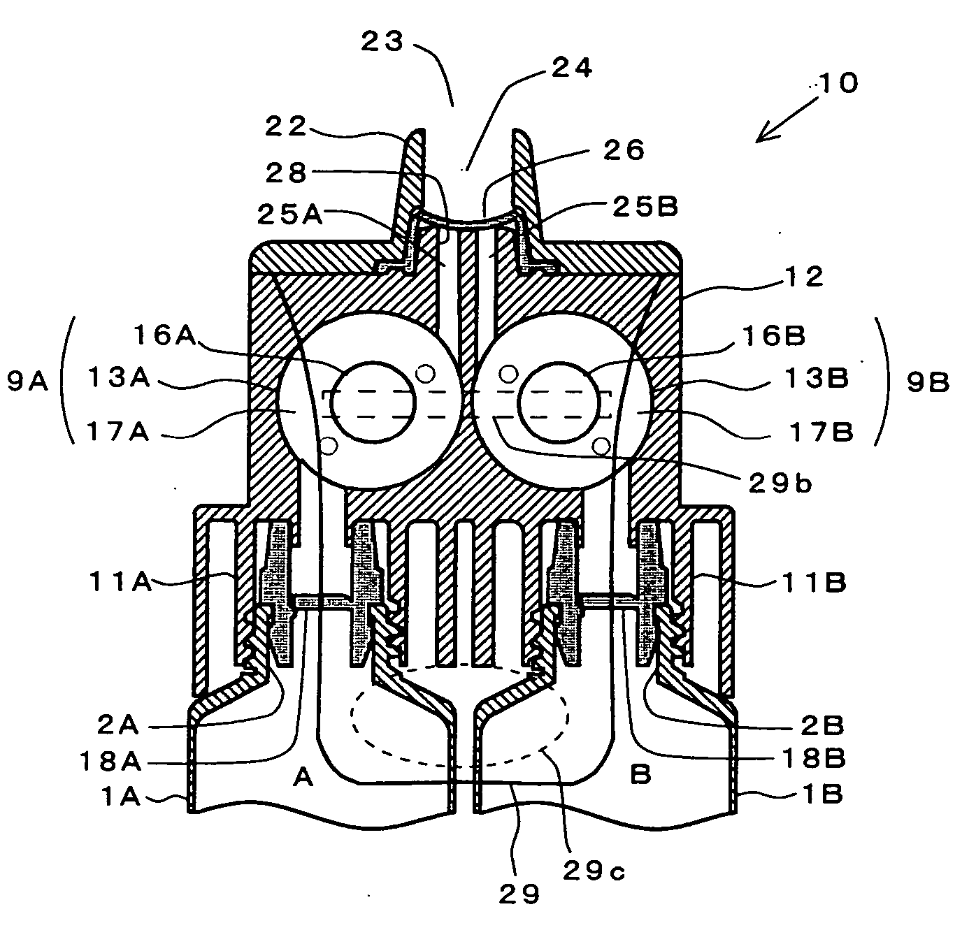
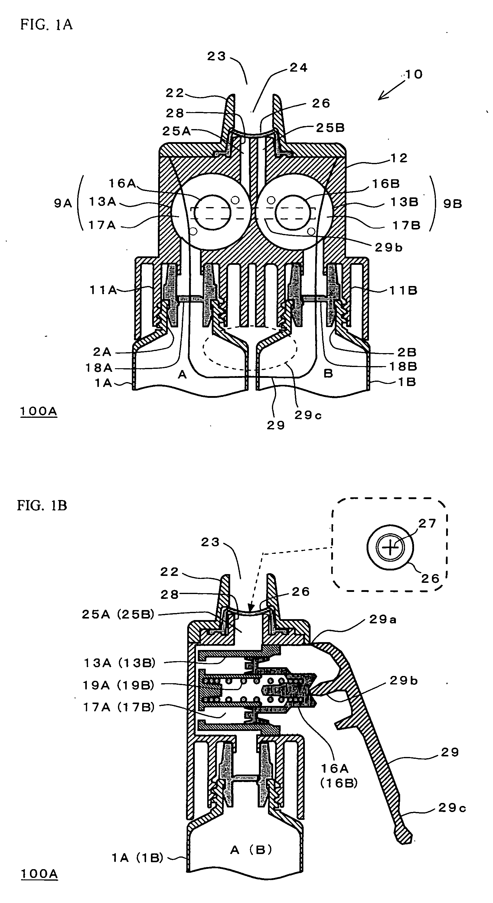
[0011] That is, the present invention provides a dispensing device that includes a plurality of containers each for accommodating a liquid content, a pump device in fluid communication with the plurality of containers, and a lever for actuating a piston of the pump device, wherein one lever operation allows the liquid contents accommodated in the respective containers to be discharged simultaneously through a discharge outlet. The pump device has, at least, a first cylinder in fluid communication with a first container, a first piston provided within the first cylinder, a second cylinder in fluid communication with a second container, and a second piston provided within the second cylinder. The lever acts upon each piston at the same time, and each liquid content discharge path in fluid communication with each cylinder communicates with one discharge valve upstream of the discharge outlet. This arrangement allows the liquid contents discharged from each cylinder to pass through the discharge valve and be discharged together.
[0013] According to the dispensing device of the present invention, a predetermined amount of each of the liquid contents accommodated respectively in a plurality of containers can be dispensed at the same time. Furthermore, the discharge valve is provided upstream of the discharge outlet, so that the discharge path of each liquid content is in fluid communication with the discharge valve. This arrangement makes it possible to prevent the liquid contents from being mixed with each other within the cylinders. The dispensing device is also designed such that only one discharge valve acts as a check valve for interrupting a backward flow opposite to the direction of discharge, thereby making it possible to reduce the number of parts and thus manufacturing costs.
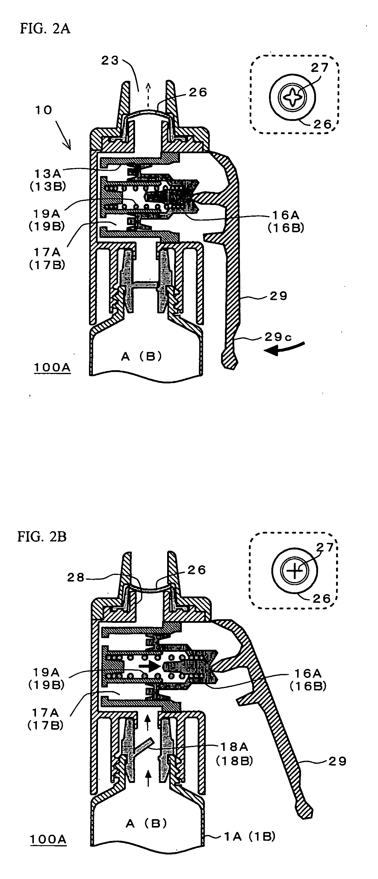
[0014] Furthermore, the dispensing device according to the present invention may also be provided with a lever type handle which acts upon the first piston and the second piston at the same time. In this case, this arrangement allows for gripping the dispensing device with one hand and placing fingers on the lever to actuate the lever with one effortless lever operation, thereby discharging the liquid contents from respective containers. That is, typically, a push button provided on an aerosol container or a pump container as a manipulation member is designed to perform a depressing operation with one finger. This arrangement is thus practically difficult to operate with multiple fingers, thereby causing a user to feel that the operation requires an effort to discharge two liquids. However, with the lever provided according to the present invention, it is possible to readily place multiple fingers on the lever for a discharge operation with an effortless force. In particular, the lever type handle can be formed to be wide in width. This arrangement would facilitate placing multiple fingers on the lever for manipulations, thereby making it possible to provide a discharge operation with a further reduced effortless force.

Problems solved by technology

However, an aerosol container is costly to manufacture.
The container also needs to be degassed and then discarded as can wastes at much expense in time and effort.
Furthermore, since the container allows the liquid content to be continuously discharged while the stem is being depressed, the discharge cannot be controlled quantitatively.
Accordingly, it can not be carried out with an effortless force to depress the discharge button with one finger to simultaneously depress the stems of the two pump devices while grasping the pump container containing two liquids with the one hand.
Accordingly, such a problem may rise that a chemical reaction between the two agents will progress in the cylinder until the container is used again.

Method used


Image

  • Dispensing device
  • Dispensing device
  • Dispensing device

Examples


Embodiment Construction

[0044] Now, the present invention will be described below in more detail with reference to the accompanying drawings. Throughout the drawings, the same reference symbols denote the same or equivalent components.

[0045] Each of FIG. 1A and FIG. 1B is a sectional view illustrating an initial state of a dispensing device 100A according to an embodiment of the present invention. Specifically, FIG. 1A is a sectional view taken in parallel to the direction of an arrangement of two containers 1A and 1B, and FIG. 1B is a sectional view taken perpendicularly to the direction of the aforementioned sectional view. FIGS. 2A, 2B, and 2C are a sectional view illustrating an operation of the dispensing device 100A.

[0046] The dispensing device 100A includes a first container 1A for accommodating a first liquid content A, a second container 1B for accommodating a second liquid content B, and a pump device 10 which caps the top of the containers 1A and 1B. Mouth portions 2A and 2B of the containers ...


PUM


Abstract

A dispensing device including a plurality of containers respectively accommodating liquid contents, and a pump device in fluid communication with the plurality of containers. The pump device includes a first cylinder in fluid communication with the first container, a first piston provided inside the first cylinder, a second cylinder in fluid communication with the second container, and a second piston provided inside the second cylinder. The pump device further includes a lever type handle that simultaneously operates the first and second pistons. Liquid content discharge paths being respectively in fluid communication with the cylinders communicate with one discharge valve upstream of a discharge outlet, allowing the liquid contents discharged from each cylinder to pass through the discharge valve to join into one.

Description

CROSS-REFERENCE TO RELATED APPLICATIONS [0001] This application is based upon and claims the benefit of priority from PCT Application No. JP / 2004 / 014383, filed on Sep. 30, 2004, and Japanese Patent Application No. 2003-346426, filed Oct. 3, 2003, the entire contents of each of which is incorporated herein by reference. FIELD OF THE INVENTION [0002] The present invention relates to a dispensing device which dispenses multiple liquid contents simultaneously by means of a pumping unit. DESCRIPTION OF THE RELATED ART [0003] Conventionally known as a two-part type,hair cosmetic is a two-part type hair dye which is composed of, e.g., a first agent containing an oxidation dye and a second agent containing an oxidizing agent such as hydrogen peroxide. Also known is a two-part type hair bleach which is composed of a first agent containing an alkaline agent and a second agent containing hydrogen peroxide. [0004] In terms of storage stability of such a hair cosmetic, the first agent and the se...

Claims


Application Information

Patent Timeline
Patent Type & Authority Applications(United States)
IPC IPC(8): B67D5/52B67D7/70A46B11/00B05B11/00
CPCA46B11/0058B05B11/0043B05B11/3011B05B11/3084B05B11/026B05B11/1011B05B11/1084
Inventor SUZUKI, HIDEYA
Owner KAO CORP
Why Eureka
Try Eureka