Suspension trailing arm
a trailing arm and suspension technology, applied in the direction of suspension interconnection system, suspension arms with a strong resistance, etc., can solve the problems of limiting the positioning of additional components that are mounted to the arms, limiting the positioning of additional components, and affecting the stability of the suspension
- Summary
- Abstract
- Description
- Claims
- Application Information
AI Technical Summary
Problems solved by technology
Method used
Image
Examples
first embodiment
[0040]FIGS. 4A and 4B show a trailing arm 232 according to the present invention to which a conventional beam-type axle 42 is mounted (FIG. 4A only). Such axles 42 are typically capable of each carrying 6 or more tons of payload in use. The trailing arm 232 is cast as a single piece and includes a front portion 252 and a rear portion 254 separated by an axle locating portion or feature in the form of a cast axle wrap 256 dimensioned to receive the axle 42 therethrough.
[0041] The leading end of the front portion 252 is cast so as to provide a bearing mounting 246 to receive a resilient bearing (not shown) that mounts the trailing arm 232 to a chassis support bracket (not shown) in a similar manner to the prior art.
[0042] The front portion 252 is cast between the axle wrap 256 and the bearing mounting 246 with an I-section profile to provide an optimum strength to weight ratio for the arm 232.
[0043] The rear portion 254 includes an upwardly facing substantially planar surface 250 up...
third embodiment
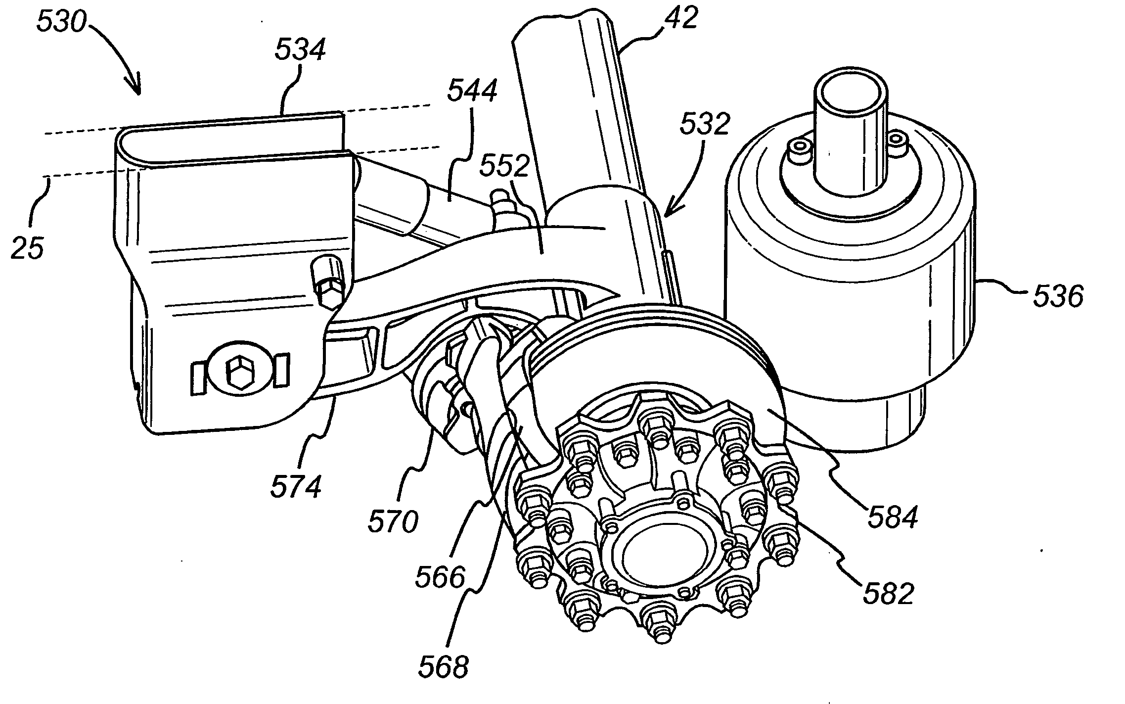
[0050] Turning now to FIGS. 6 and 7, the present invention is illustrated. As before, like numerals where possible designate like parts, but with the with the prefix “3” being replaced by the prefix “4.”
[0051] In this embodiment, a further variant of a trailing arm 432 is illustrated in situ in a suspension assembly 430. The arm 432 is cast as a single piece and is pivoted at its leading end to a chassis support bracket 434 by a bearing (not visible) mounted in a housing 446. A damper 444 extends between the bracket 434 and a mounting feature in the form of a mounting hole 485 provided in a front portion 452 of the arm 432.
[0052] An axle wrap 456 includes an extension 462 in a direction outwardly towards the end of the axle 442 and a bracket 464 is cast integrally therewith in a direction radially outwardly from the axle wrap 456 to enable a carrier portion 466 of a disc brake to be secured thereto by bolts 472. In turn, a floating caliper 468 of the disc brake is mounted to the ca...
sixth embodiment
[0061]FIGS. 19, 20, 21, 22, 23, 24, 24A and 24B illustrate the present invention in which like numerals where possible designate like parts, but with the prefix “7” replacing the prefix “6.”
[0062] The arm of the sixth embodiment is similar in many respects to the arm of the second embodiment in that it is formed from a separate front section 752 and a rear section 754 that are joined together by transverse welds at edges 760 of a front axle wrap portion 756a and a rear axle wrap portion 756b.
PUM
 Abstract
Description
Claims
Application Information
 - R&D
- Intellectual Property
- Life Sciences
- Materials
- Tech Scout
- Unparalleled Data Quality
- Higher Quality Content
- 60% Fewer Hallucinations
Browse by: Latest US Patents, China's latest patents, Technical Efficacy Thesaurus, Application Domain, Technology Topic, Popular Technical Reports.
© 2025 PatSnap. All rights reserved.Legal|Privacy policy|Modern Slavery Act Transparency Statement|Sitemap|About US| Contact US: help@patsnap.com


