Battery protection IC chip

a technology of ic chip and battery, applied in the direction of safety/protection circuit, coupling device connection, instruments, etc., can solve the problems of high risk of trouble and likely troubles of lithium-ion batteries, and achieve the effect of accurate temperature detection

Active Publication Date: 2006-07-27
MITSUMI ELECTRIC CO LTD
View PDF3 Cites 32 Cited by
  • Summary
  • Abstract
  • Description
  • Claims
  • Application Information

AI Technical Summary

Benefits of technology

[0009] According to the present invention, the battery protection IC chip is mounted on the charge control FET chip and the discharge control FET chip. As the battery protection IC chip is adjacent to the charge control FET chip and the discharge control FET chip, the temperature detector can accurately detect the temperature of the charge control FET chip and the discharge control FET chip.

Problems solved by technology

Lithium-ion batteries are likely to have troubles in the event of overcharge, overdischarge, and overcurrent.
There is a high risk of trouble if an overcurrent is applied to a lithium-ion battery from a recharger during charging, or if an overcurrent is applied to a mobile device from a lithium-ion battery during use of the mobile device.

Method used


Image

  • Battery protection IC chip
  • Battery protection IC chip
  • Battery protection IC chip

Examples


first embodiment

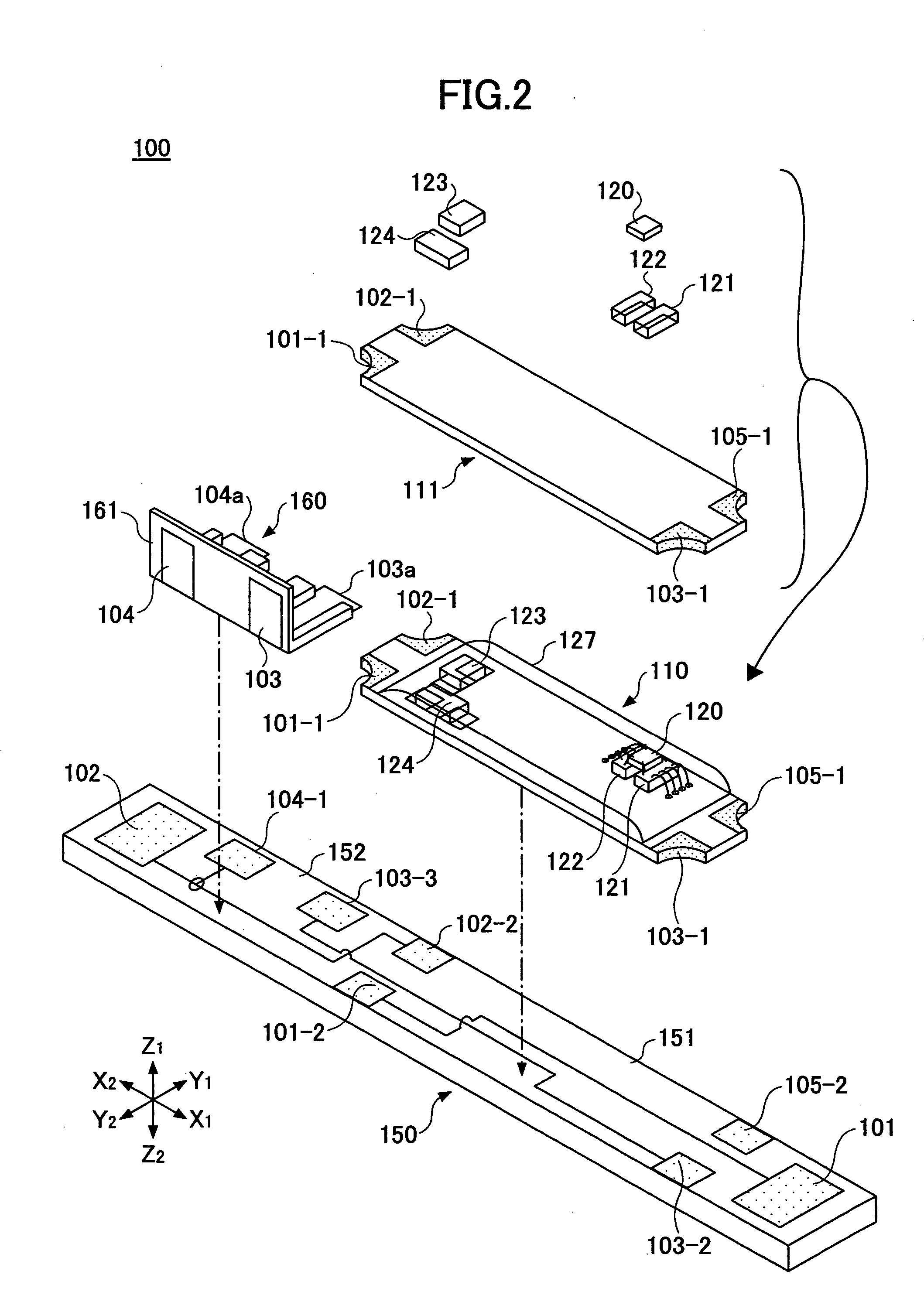
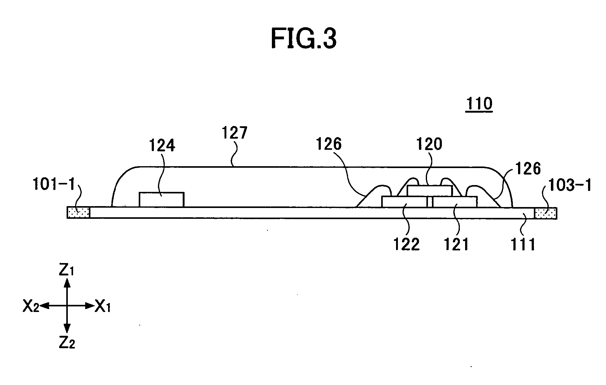
[0024]FIGS. 1 and 2 illustrate a battery protection device 100 according to a first embodiment of the present invention. FIG. 3 illustrates a COB type battery protection module 110. FIG. 8 and FIG. 9 illustrate a battery pack 200 in which the battery protection device 100 connected to a lithium-ion battery 201 is installed. In FIGS. 8 and 9, Z1 indicates an inner side of the battery pack 200, and Z2 indicates a front side of the battery pack 200. X1-X2 indicates a length direction of the battery protection device 100; Y1-Y2 indicates a width direction thereof; and Z1-Z2 indicates a thickness direction thereof. The Z1 side of the battery protection device 100 is the upper side, and the Z2 side thereof is the lower side. FIG. 10 is a circuit diagram of the battery protection device 100.

[0025] Referring to FIGS. 1 and 2, the battery protection device 100 comprises a battery protection module 110, a base printed board 150, and a connector member 160. The battery protection module 110 a...

second embodiment

[0046] In a second embodiment, the control IC chip 120 and the first and second FET-SW chips 121 and 122 of the first embodiment are integrated into one module.

[0047]FIG. 11 shows a control IC chip module 300 serving as a battery IC chip module. In the control IC chip module 300, first and second FET-SW chips 121 and 122 are mounted side-by-side on a board 301 having terminals 302. A control IC chip 120 is secured onto the adjacent first and second FET-SW chips 121 and 122 with a double-sided adhesive tape so as to extend across the first and second FET-SW chips 121 and 122. Au wires 126-1 through 126-5 are provided with their ends bonded. The control IC chip 120, the first and second FET-SW chips 121 and 122, and the Au wires 126-1 through 126-5 are encapsulated by a synthetic resin part 310.

[0048] Referring to FIGS. 12 and 13, the control IC chip module 300 is mounted on a COB-compatible printed board 111A together with a resistance chip 123 and a capacitor chip 124. The resista...


PUM


Abstract

A lithium-ion battery protection module is disclosed. The lithium-ion battery protection module includes a control IC chip. The control IC chip includes a discharge overcurrent detector, a charge overcurrent detector, and a temperature detector. The control IC chip is mounted on a charge control FET and a discharge control FET so as to highly accurately detect the temperature of the charge control FET and the discharge control FET.

Description

BACKGROUND OF THE INVENTION [0001] 1. Field of the Invention [0002] The present invention relates to a battery protection IC chip, and particularly relates to a battery protection IC chip that constitutes a battery pack protection circuit capable of preventing a lithium-ion battery used as a power source for a mobile device from overcharge, overdischarge, and overcurrent. [0003] 2. Description of the Related Art [0004] Many mobile devices employ lithium-ion batteries in their battery packs. Lithium-ion batteries are likely to have troubles in the event of overcharge, overdischarge, and overcurrent. Therefore, battery packs for lithium-ion batteries are provided with battery protection modules including battery protection circuits that prevent lithium-ion batteries from overcharge, overdischarge, and overcurrent. Such a battery protection circuit has a FET chip serving as an electronic switch that opens in response to overcharge, overdischarge, and overcurrent. The battery protection...

Claims


Application Information

Patent Timeline
Patent Type & Authority Applications(United States)
IPC IPC(8): H02J7/04
CPCH02J7/0031H02J7/0091H01L2224/48091H01L2224/48145H01L2224/45144H01L2924/00014H01L2924/00H02J7/00309H02J7/007192H01L2924/00012H01R12/71H01M50/572H01M50/20H01M10/48
Inventor OOSHITA, KAZUHIROIKEUCHI, AKIRANAKANO, ITSUKI
Owner MITSUMI ELECTRIC CO LTD
Why Eureka
Try Eureka