Pseudo-synchronization of the transportation of data across asynchronous clock domains

a technology of asynchronous clock domain and data transportation, applied in the field of electronic circuits, can solve the problems of normal control circuit delays, delays in data transfer between blocks, and delays in data transfer

Active Publication Date: 2006-07-27
VIA TECH INC
View PDF3 Cites 56 Cited by
  • Summary
  • Abstract
  • Description
  • Claims
  • Application Information

AI Technical Summary

Benefits of technology

[0008] Embodiments of the present disclosure provide systems and methods for pseudo-synchronization of the transportation of data across asynchronous clock domains. Briefly described, in architecture, one embodiment of the system, among others, can be implemented as follows. A method of transporting data between a first device operating at a first frequency and a second device operating at a second frequency can be achieved by pseudo-synchronizing an enable signal from the first device with an enable signal from the second device such that the pseudo-synchronized enable signals can be captured by logic elements operating at either of the first and second clock frequencies; reading data enabled by a first pseudo-synchronized enable signal from a first device into a temporary storage element; and writing data from the temporary storage element to a second device enabled by a second pseudo-synchronized enable signal; wherein one of the first and second frequency is an integral multiple of the other of the first and second frequency.

Problems solved by technology

However, when the read control signal and the write control signal are synchronized, penalties are incurred in the form of delays.
The read and write blocks, which are sharing the data, are often clocked at different frequencies, which introduces unwanted delays in the transfer of data between the blocks.
The delays are normally incurred in the control circuit.
A delay is incurred when the read control signal is synchronized with the write control signal.
Since the write signal fills the FIFO faster than the read signal can empty it, some delay is incurred.
Thus, a heretofore unaddressed need exists in the industry to address the aforementioned deficiencies and inadequacies.

Method used


Image

  • Pseudo-synchronization of the transportation of data across asynchronous clock domains
  • Pseudo-synchronization of the transportation of data across asynchronous clock domains
  • Pseudo-synchronization of the transportation of data across asynchronous clock domains

Examples


Embodiment Construction

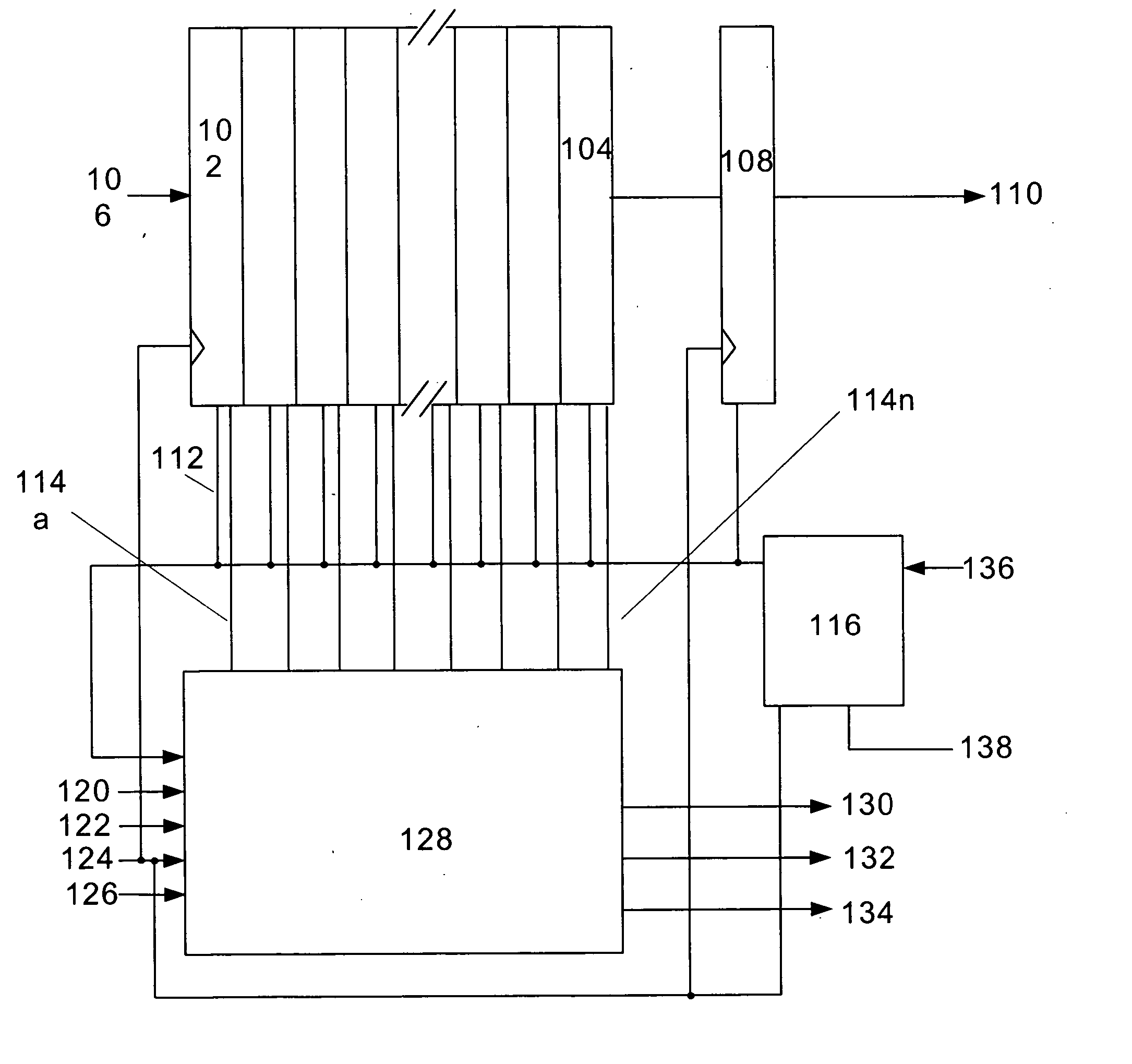
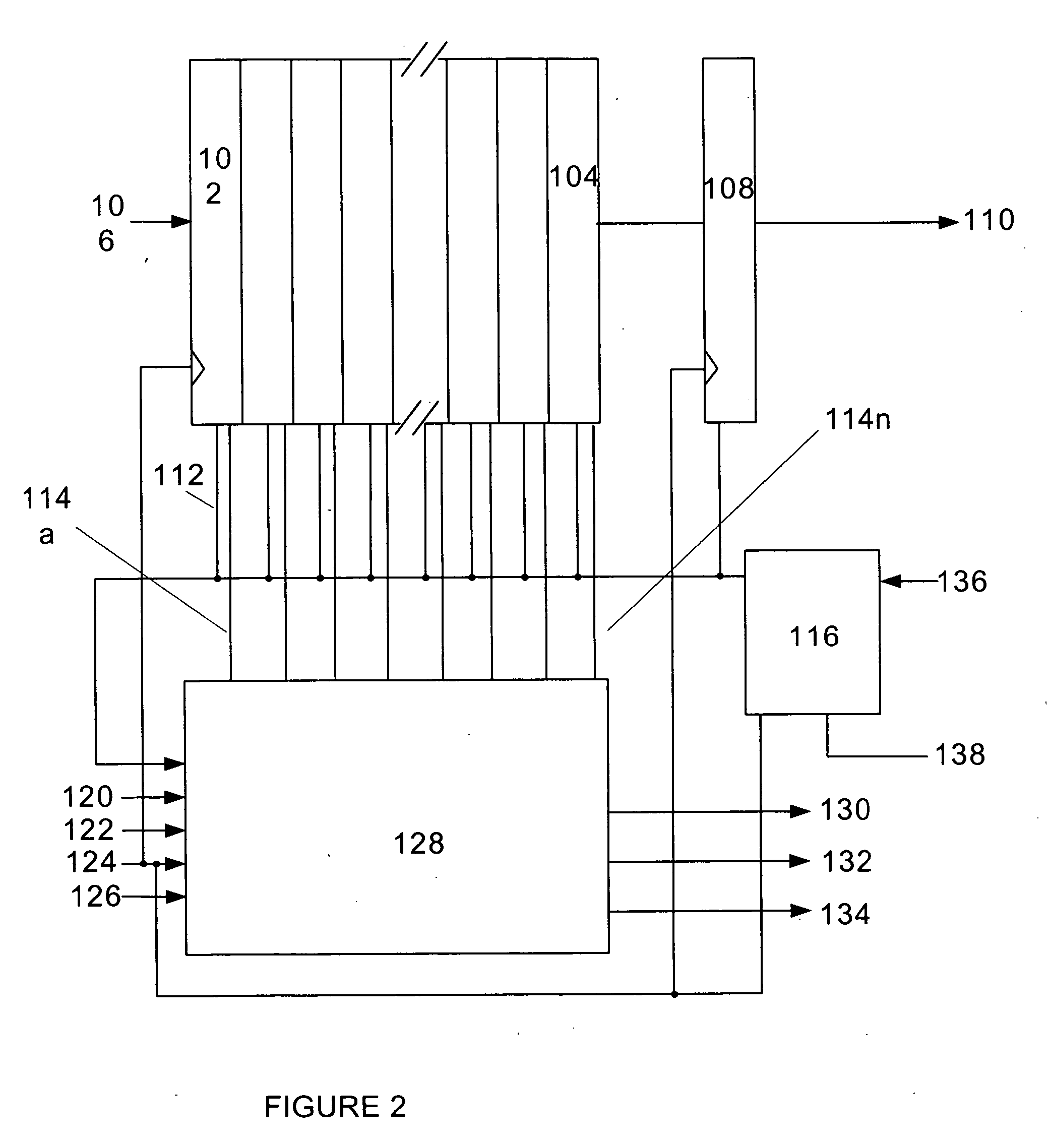
[0017] Disclosed herein are systems and methods for pseudo-synchronous data transfer. To facilitate description of the inventive systems, example systems that can be used to implement the systems and methods for pseudo-synchronous data transfer are discussed with reference to the figures. Although these systems are described in detail, it will be appreciated that these systems are provided for purposes of illustration only and modifications are feasible without departing from the inventive concept.

[0018] Referring now and in more detail to the drawings in which like numerals indicate corresponding parts through the several views, this disclosure describes pseudo-synchronous data transfer. It describes how the system is configured and how it operates.

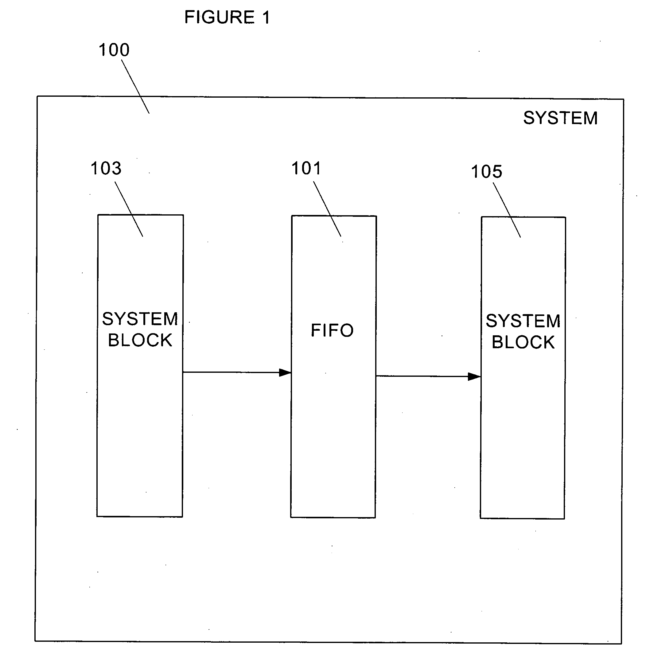
[0019] A system level block diagram 100 is provided in FIG. 1. FIFO 101 is used to transport data between system block 103 and system block 105. System blocks 103, 105 operate at different frequencies. The frequencies of a preferred em...


PUM


Abstract

A pseudo-synchronous temporary storage element transports data between two system blocks with different clock systems by pseudo-synchronizing the clock edges of the two clock signals. The pseudo-synchronization circuit may be an integral part of a storage element, a separate pseudo-synchronization device, or a discrete add-on circuit to an off the shelf storage element device.

Description

TECHNICAL FIELD [0001] The present disclosure is generally related to electronic circuits and, more particularly, is related to systems and methods for pseudo-synchronizing the transportation of data across asynchronous clock domains. BACKGROUND OF THE DISCLOSURE [0002] A FIFO is a first in, first out, temporary data storage device. It is useful for sharing data between real-time tasks and user-level applications. A FIFO is often used to connect a non-real-time machine interface to a real-time application (e.g. to log messages to disk files). [0003] A FIFO in its simplest form is a queue of raw storage units. Typically, fixed-size data structures are written to a FIFO, so that a device reading the data is not burdened with message boundaries. The queued nature of a FIFO makes it best suited for ordered streams of data such as: messages or error diagnostics where the message can include a timestamp for later analysis; data logs for performance metrics; and configuration information a...

Claims


Application Information

Patent Timeline
Patent Type & Authority Applications(United States)
IPC IPC(8): G11C7/00
CPCG06F5/06G06F13/4059
Inventor FUNG, HON CHUNG
Owner VIA TECH INC
Why Eureka
Try Eureka