Methods and apparatuses for cutting dough utilizing a shaped opening

a technology of shaped openings and cutting methods, applied in the field of methods and apparatuses for cutting dough, can solve the problems of high cost, inability to design and purchase new dough cutters for each new shape, and relatively complex dough products with non-uniform shapes

Active Publication Date: 2006-07-27
LOWRY STANLEY N +2
View PDF21 Cites 13 Cited by
  • Summary
  • Abstract
  • Description
  • Claims
  • Application Information

AI Technical Summary

Benefits of technology

[0073] In the embodiment shown, the head also comprises an o-ring 60. While an embodiment utilizing an o-ring is shown, other shapes can be used. Also, in some embodiments no o-ring is used. In an embodiment comprising an o-ring, the o-ring may provide some resistance, which can provide a cue to an operator regarding alignment of the removable die in relation to the head 6. The o-ring 60 may also assist in maintaining the position of the removable die. The o-ring 60 can be constructed from food-grade materials known to those of skill in the art. An example of a commercially available o-ring useful in embodiments of the present invention is part number H70FDA223 from Applied Industrial Technologies of Cleveland, Ohio.
[0074]FIG. 4B is a cross-sectional view drawing of a head in one embodiment of the present invention. The o-ring 60 can be positioned in a groove 61 in a first end 62 of the head 6. In the embodiment shown, the o-ring 60 and groove 61 can be selected or designed such that a portion of the o-ring 60 extends above the side walls of the groove 61 when the o-ring 60 is positioned in the groove 61. For example, the o-ring 60 may be larger than the depth of the groove 61. By having a portion of the o-ring 60 extend above the side walls of the groove 61, the o-ring 60 can assist in securing the removable die 10 to the head 6.
[0075] In the embodiment shown in FIG. 4B, the groove 61 is angled away from the shaped opening 14 to help ensure that the o-ring 60 stays in the groove 61. The groove also has a beveled edge 63 to help avoid compromising or damaging the o-ring 61.
[0076] The bottom of the removable die 10 may also comprise a groove that can have approximately the same circumference as the o-ring 60. When the removable die 10 is coupled to the head 6, the bottom of the removable die 10 slides over the first end 62 of the head 6. In doing so, the bottom of the removable die 10 will also slide over the o-ring 60 positioned in the grove of the head 6. The removable die 10 experiences some resistance as it slides over the head 6 due to the o-ring 60 extending out of the groove (the o-ring 60 may compress to some extent as the removable die 10 slides over it). When the groove in the bottom of the removable die 10 is positioned over the o-ring 60, the o-ring 60 can expand into the groove 460 in the removable die 10 since the groove has approximately the same circumference as the o-ring 60 in this embodiment. The o-ring 60, in this embodiment, helps to secure the removable die 10 to the head 6 as it can be positioned in both the groove in the head 6 and the groove in the removable die 10. This alignment makes it difficult for the removable die 10 to slide since the o-ring 60 must be compressed from its extended position in the groove of the removable die 10. This embodiment of the present invention advantageously provides a way of securing a head to a removable die that prevents slipping of the removable die without requiring the use of a fastener, such as a screw. Further, this embodiment also provides a convenient way for removable dies to be changed or replaced.

Problems solved by technology

As dough-based products have traditionally been extruded and cut as substantially uniform shapes, the production of dough-based products having relatively complex and / or non-uniform shapes could require the purchase and design of new dough cutters for each new shape, which could be expensive.

Method used


Image

  • Methods and apparatuses for cutting dough utilizing a shaped opening
  • Methods and apparatuses for cutting dough utilizing a shaped opening
  • Methods and apparatuses for cutting dough utilizing a shaped opening

Examples


Embodiment Construction

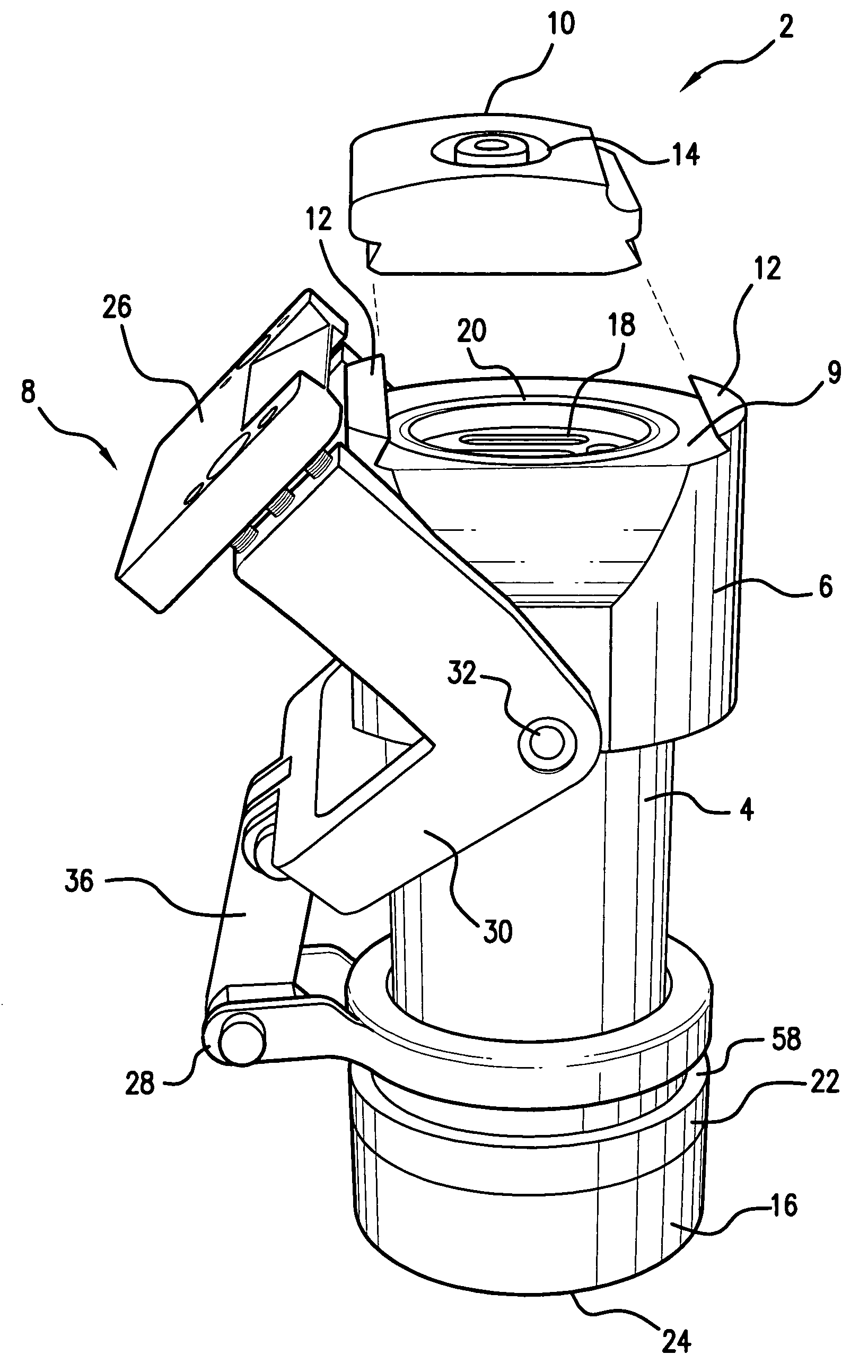
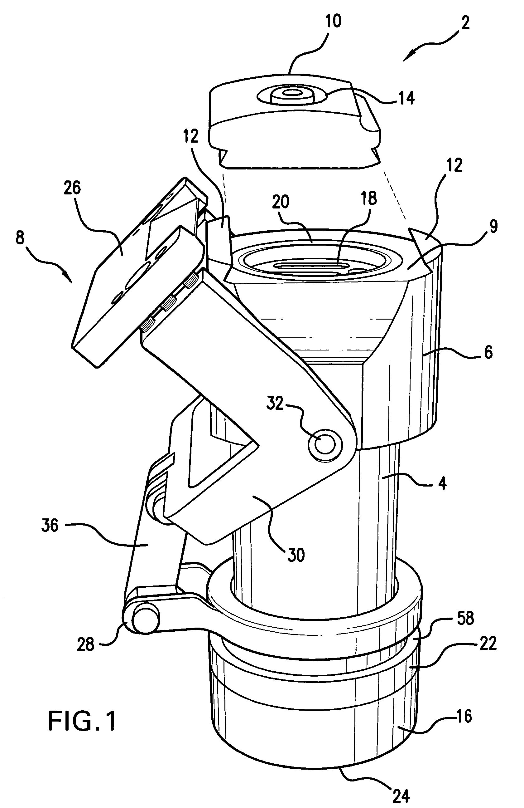
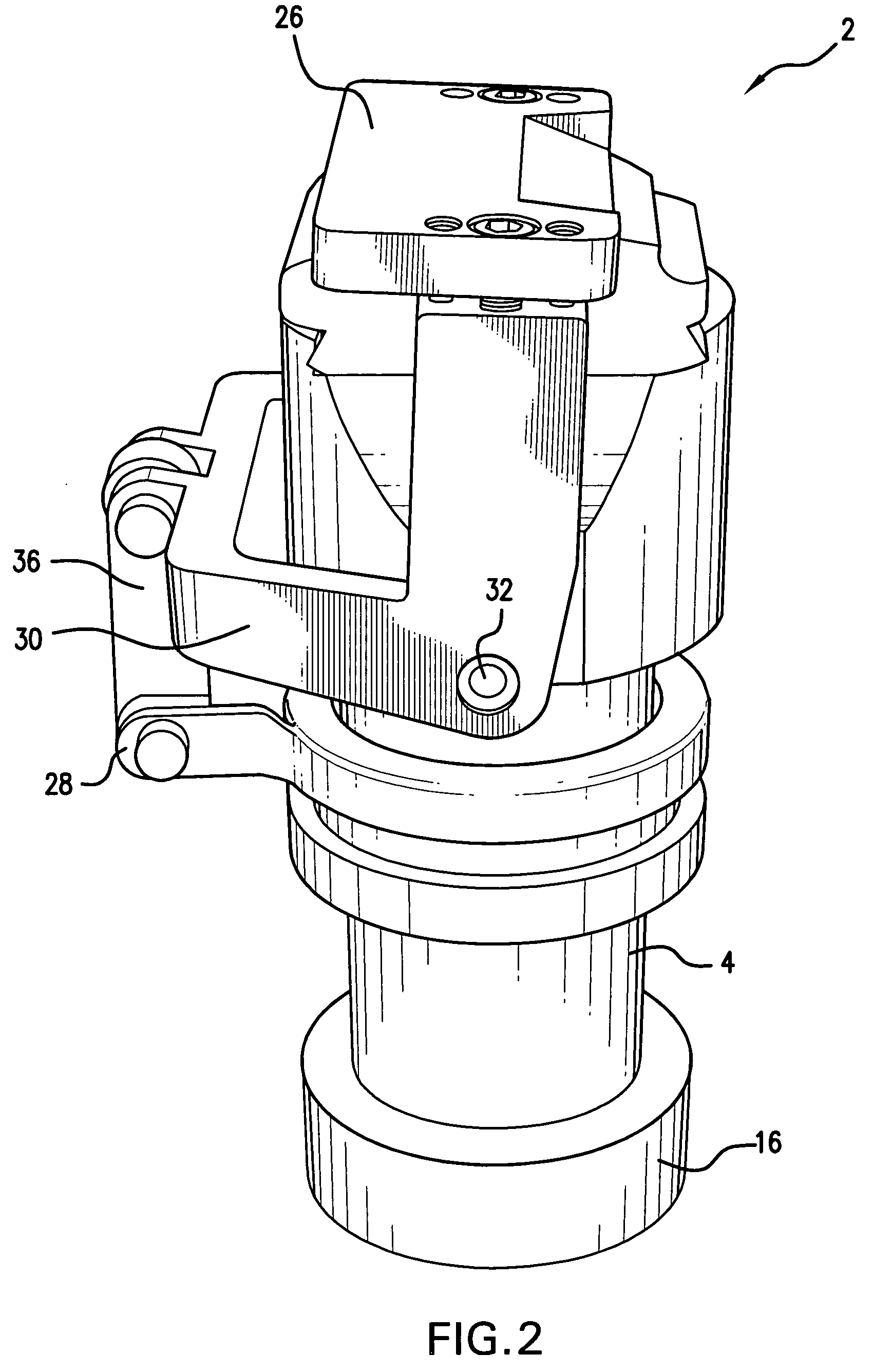
[0029] Embodiments of the present invention provide methods and apparatuses for cutting dough. More particularly, embodiments of the present invention relate to methods and apparatuses for cutting dough to form dough-based products having a variety of shapes. In one embodiment, a dough cutting apparatus according to the present invention comprises a barrel having two ends, a removable die comprising a shaped opening, the removable die adapted to be coupled to a first end of the barrel, and a knife adapted to cut dough extruded from the shaped opening.

Introduction

[0030] One embodiment of the present invention comprises a dough cutter configured to create “doughnut shells.” As used herein, “doughnut shells” refer to doughnuts that do not have hollow center portions, but may have a soft interior that can be filled with jelly, custard, whipped cream, or other fillings. If filled, a filling is injected into a doughnut shell; the filling moves the internal structure of the doughnut towa...


PUM

PropertyMeasurementUnit
shapesaaaaaaaaaa
of symmetryaaaaaaaaaa
symmetryaaaaaaaaaa

Abstract

Methods and apparatuses for cutting dough are described. One described dough cutting apparatus comprises a barrel having two ends, a removable die comprising a shaped opening, the removable die adapted to be coupled to a first end of the barrel, and a knife adapted to cut dough extruded from the shaped opening. In one illustrative method for making doughnuts, dough is extruded and cut using such a dough cutting apparatus and the dough is then cooked.

Description

RELATED APPLICATIONS [0001] This application claims priority to Application Ser. No. 60 / 609,929, filed on Sep. 15, 2004, titled “Methods and Apparatuses for Cutting Dough,” the entirety of which is incorporated herein by reference.FIELD OF THE INVENTION [0002] The present invention relates generally to methods and apparatuses for cutting dough. More particularly, embodiments of the present invention relate to methods and apparatuses for cutting dough to form dough-based products having a variety of shapes. BACKGROUND OF THE INVENTION [0003] Doughnut production involves mixing and extruding dough and then frying the dough. In some non-limiting processes, dough is cut and dropped onto a belt or tray and transported through a proofer to a frying apparatus for cooking. After cooking, the dough-based product may be glazed, filled, and / or decorated to make the final doughnut. Other processes for making doughnuts are also known. [0004] An apparatus for extruding dough is often referred to ...

Claims


Application Information

Patent Timeline
Patent Type & Authority Applications(United States)
IPC IPC(8): A23P1/00B29C48/30
CPCA21C11/16A21C11/166A21C3/04A21C3/10A21C5/00A21C5/08A21C7/06A21C11/10B29C33/0038B29C33/0044B29C33/30B29C33/305B29C33/306B29C33/307
Inventor LOWRY, STANLEY N.MCCALL, GARCIE M.ROTH, CHRISTOPHER T.
Owner LOWRY STANLEY N
Why Eureka
Try Eureka