Method and apparatus for processing polynucleotide-containing samples

Active Publication Date: 2006-07-27
HANDYLAB
View PDF104 Cites 258 Cited by
  • Summary
  • Abstract
  • Description
  • Claims
  • Application Information

AI Technical Summary

Benefits of technology

[0059] The flexible wall of the reservoir can limit or prevent leaching of chemicals therethrough. The res

Problems solved by technology

However, the functioning of enzymes used in such techniques may be inhibited by the presence of inhibitors present along with th

Method used


Image

  • Method and apparatus for processing polynucleotide-containing samples
  • Method and apparatus for processing polynucleotide-containing samples
  • Method and apparatus for processing polynucleotide-containing samples

Examples


example 1

Preparing Retention Member

[0229] Carboxylate surface magnetic beads (Sera-Mag Magnetic Carboxylate modified, Part #3008050250, Seradyn) at a concentration of about 1011 mL−1 were activated for 30 minutes using N-hydroxylsuccinimide (NHS) and 1-ethyl-3-(3-dimethylaminopropyl) carbodiimide (EDAC) in a pH 6.1 500 mM 2-(N-Morpholinio)-ethanesulfonic acid (MES) buffer solution. Activated beads were incubated with 3000 Da or 300,000 Da average molecular weight poly-L-lysine (PLL). After 2 washes to remove unbound PLL, beads were ready for use.

example 2

Microfluidic Device

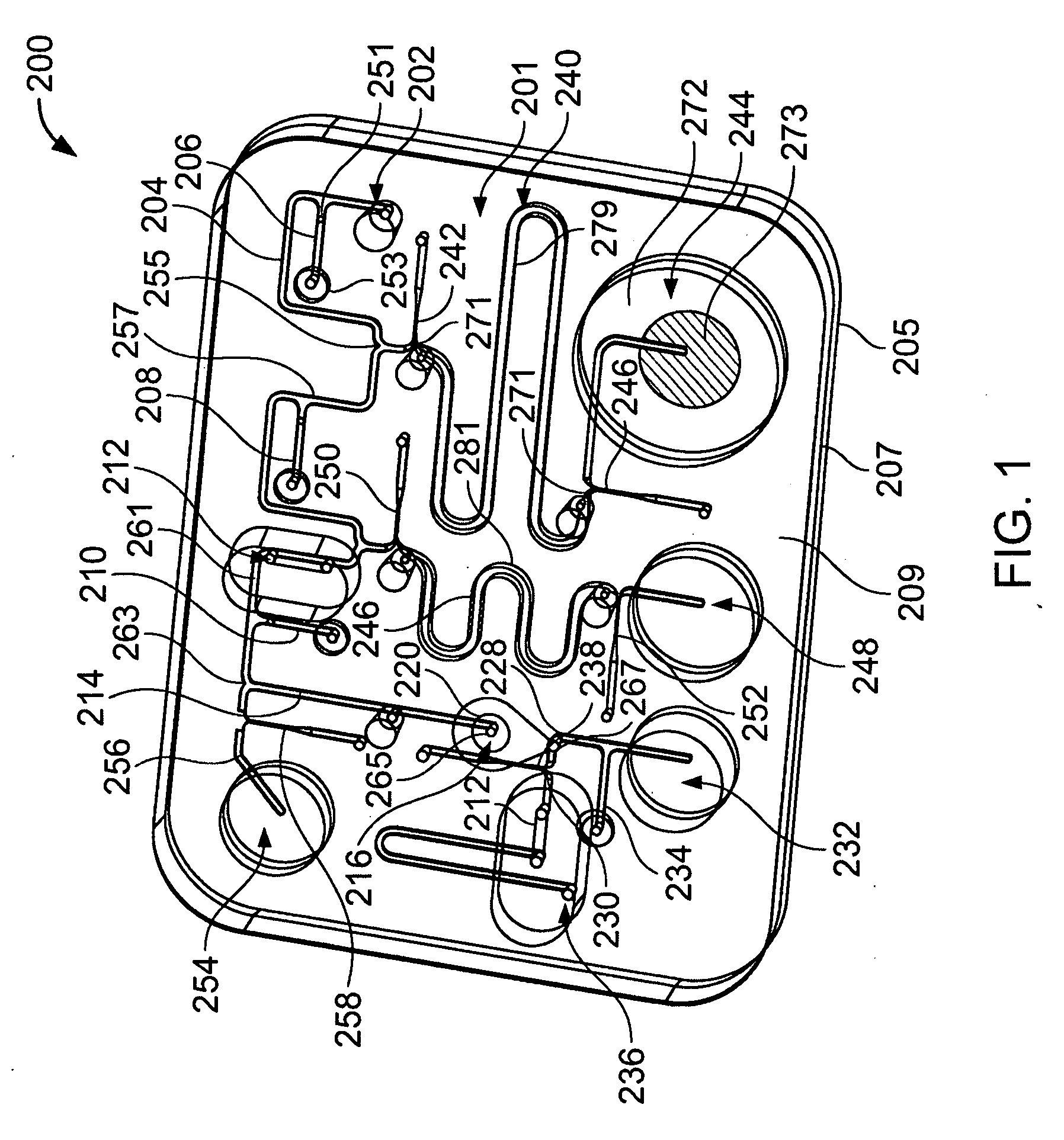
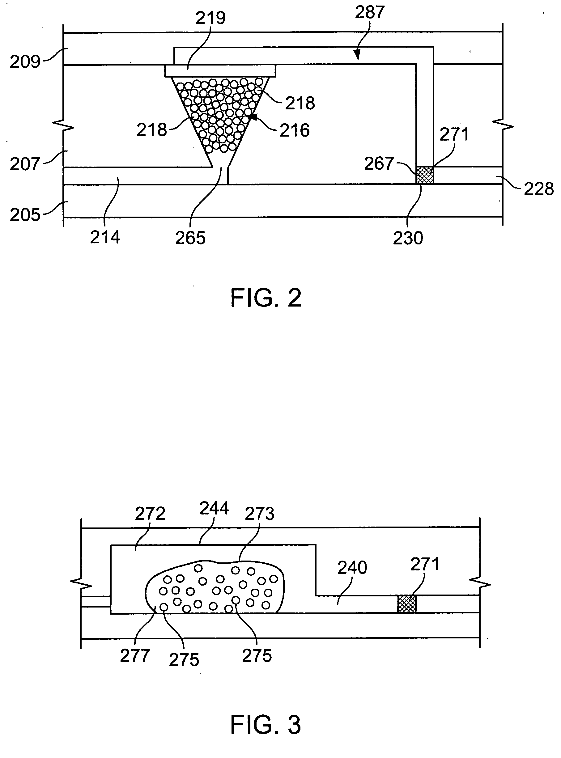
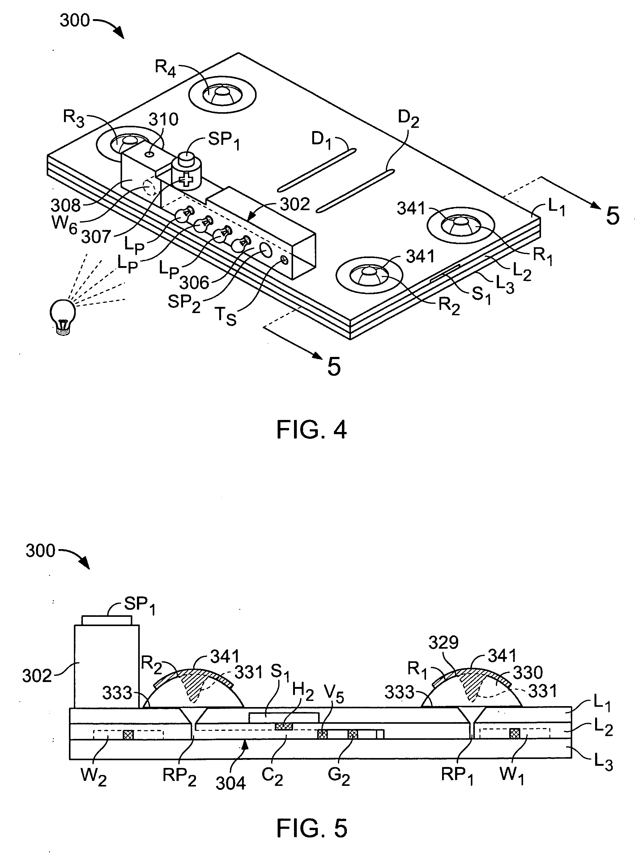
[0230] Referring to FIGS. 20 and 21, a microfluidic device 300 was fabricated to demonstrate separation of polynucleotides from inhibitors. Device 300 comprises first and second substrate portions 302′, 304′, which respectively comprise first and second layers 302a′, 302b′ and 304a′, 304b′. First and second layers 302a′, 302b′ define a channel 306′ comprising an inlet 310′ and an outlet 312′. First and second layers 304a′, 304b′ define a channel 308′ comprising an inlet 314′ and an outlet 316′. First and second substrate portions 302′, 304′ were mated using adhesive 324′ so that outlet 312′ communicated with inlet 314′ with a filter 318′ positioned therebetween. A portion of outlet 312′ was filed with the activated beads prepared above to provide a processing region 320′ comprising a retention member (the beads). A pipette 322′ (FIG. 22) secured by adhesive 326′ facilitated sample introduction.

[0231] In use, sample introduced via inlet 310′ passed along channel ...

example 3

Retention of DNA

[0232] Retention of polynucleotides by the poly-L-lysine modified beads of device 300′ was demonstrated by preparing respective devices comprising processing regions having a volume of about 1 μL including about 1000 beads. The beads were modified with poly-L-lysine of between about 15,000 and 30,000 Da. Each processing region was filled with a liquid comprising herring sperm DNA (about 20 uL of sample with a concentration of about 20 mg / mL) thereby placing the beads and liquid in contact. After the liquid and beads had been in contact for 10 minutes, the liquid was removed from each processing region and subjected to quantitative real-time PCR to determine the amount of herring sperm DNA present in the liquid.

[0233] Two controls were performed. First, an otherwise identical processing region was packed with unmodified beads, i.e., beads that were identical with the poly-L-lysine beads except for the activation and poly-L-lysine incubation steps. The liquid compris...


PUM

PropertyMeasurementUnit
Temperatureaaaaaaaaaa

Abstract

Methods and systems for processing polynucleotides (e.g., DNA) are disclosed. A processing region includes one or more surfaces (e.g., particle surfaces) modified with ligands that retain polynucleotides under a first set of conditions (e.g., temperature and pH) and release the polynucleotides under a second set of conditions (e.g., higher temperature and/or more basic pH). The processing region can be used to, for example, concentrate polynucleotides of a sample and/or separate inhibitors of amplification reactions from the polynucleotides. Microfluidic devices with a processing region are disclosed.

Description

CLAIM OF PRIORITY [0001] This application is a continuation-in-part of international application no. PCT / US2005 / 015345, filed May 3, 2005, and claims the benefit of priority of U.S. provisional application Nos. 60 / 567,174, filed May 3, 2004, and Ser. No. 60 / 645,784, filed Jan. 21, 2005. Each of these applications is incorporated herein by reference in its entirety.FIELD OF THE INVENTION [0002] The present invention relates to methods for processing polynucleotide-containing samples as well as to related systems. BACKGROUND [0003] The analysis of a biological sample often includes detecting one or more polynucleotides present in the sample. One example of detection is qualitative detection, which relates, for example, to the determination of the presence of the polynucleotide and / or the determination of information related to, for example, the type, size, presence or absence of mutations, and / or the sequence of the polynucleotide. Another example of detection is quantitative detectio...

Claims


Application Information

Patent Timeline
IPC IPC(8): C12Q1/68C12M1/34B01F5/06B01F13/00B01L3/00B01L3/14B01L7/00C12N15/10F16K99/00
CPCB01L3/502707F16K2099/0084B01L3/502723B01L3/502738B01L3/523B01L7/52B01L2200/16B01L2300/0672B01L2300/0816B01L2300/0867B01L2400/0442B01L2400/0481B01L2400/0487B01L2400/0633B01L2400/0683F16K99/0001F16K99/0019F16K99/0034F16K99/0044B01L3/502715C12N15/101B01L3/50273B01L3/502753B01L3/5082B01L3/565B01L2200/10B01L2300/087B01L2300/0887B01L2400/0677B01L2400/0694C12N15/1006C12Q1/6806F16K99/0032F16K99/0036B01F25/4331B01F25/433B01F33/30C12Q2565/629C12Q1/686
Inventor WU, BETTYALTHAUS, JOHN S.PHADKE, NIKHILBRAHMASANDRA, SUNDARESH N.HANDIQUE, KALYANKEHRER, AARONPARUNAK, GENEHALEY, CECELIASPRINGER, TED
Owner HANDYLAB
Why Eureka
Try Eureka