Laser cladding apparatus and method

a technology of laser cladding and processing equipment, which is applied in the direction of machine/engine, manufacturing tools, and solventing equipment, etc., can solve the problems of reducing the yield ratio of powder materials, requiring a large amount of equipment investment, and requiring a large amount of facility-installation space, so as to reduce the cost of facility, reduce the effect of facility-installation space and simplify the constituent elements of laser cladding processing equipmen

Active Publication Date: 2006-08-03
TOYOTA JIDOSHA KK
View PDF8 Cites 53 Cited by
  • Summary
  • Abstract
  • Description
  • Claims
  • Application Information

AI Technical Summary

Benefits of technology

[0021] In the present invention, the cylinder head is fixed, and the laser-processing head is rotated around the central axial line of the valve seat while it is inclined, and thereby it is possible to form a clad layer on the inclined valve-seat surface.
[0022] Therefore, since it is possible to simplify the constituent elements of laser-clad processing apparatus remarkably compared with the prior art, it is possible to reduce the facility cost by half compared with the prior art. Moreover, it is possible to reduce the facility-installation space remarkably (by about ⅓).
[0023] Since the laser-clad processing apparatus of the present invention uses a semiconductor laser, the laser efficiency is high compared with prior-art apparatuses by means of CO2 laser method. Therefore, it is possible to cut the electric-power cost remarkably (by ⅕ approximately). Moreover, since the periodic replacement of laser gas is unnecessary similarly to the CO2 laser method, and further since the replacement of component parts, and the like, is easy, it is possible to reduce the maintenance cost greatly.
[0024] In prior-art apparatuses by means of CO2 laser method, a laser beam is such that, be...

Problems solved by technology

In addition to firmly positioning and holding the cylinder head, such a heavy-weight object, in order to rotate this smoothly, a huge facility as shown in FIG. 25 becomes necessary so that a great deal of equipment investment and facility-installation space have been required.
Moreover, the powdery material, which has remained on the valve-seat portion without ...

Method used


Image

  • Laser cladding apparatus and method
  • Laser cladding apparatus and method
  • Laser cladding apparatus and method

Examples


Embodiment Construction

[0041] An embodiment mode of the present invention will be hereinafter described in detail with reference to the drawings. Note that like symbols shall designate like parts or corresponding parts.

Laser-Clad Processing Apparatus

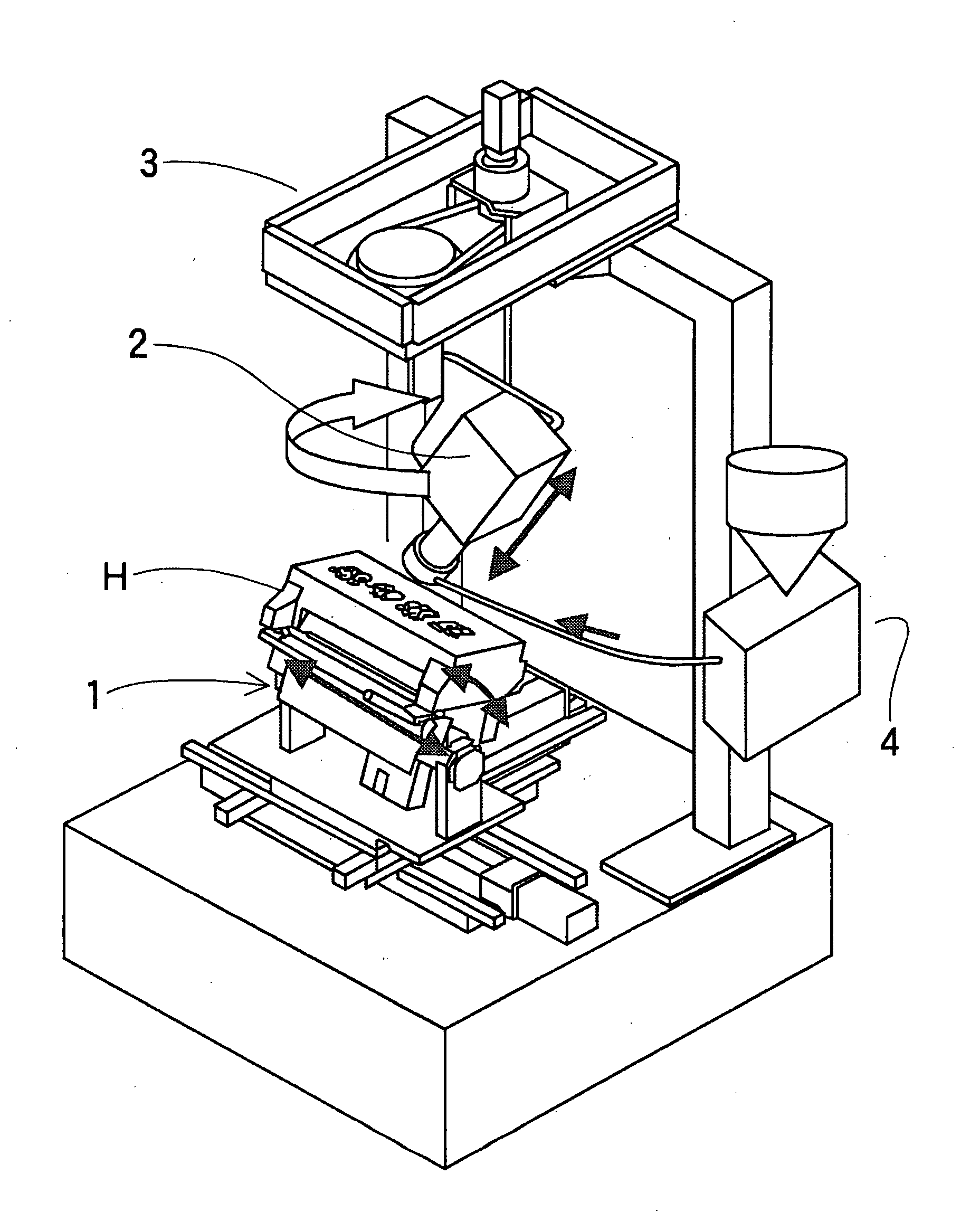
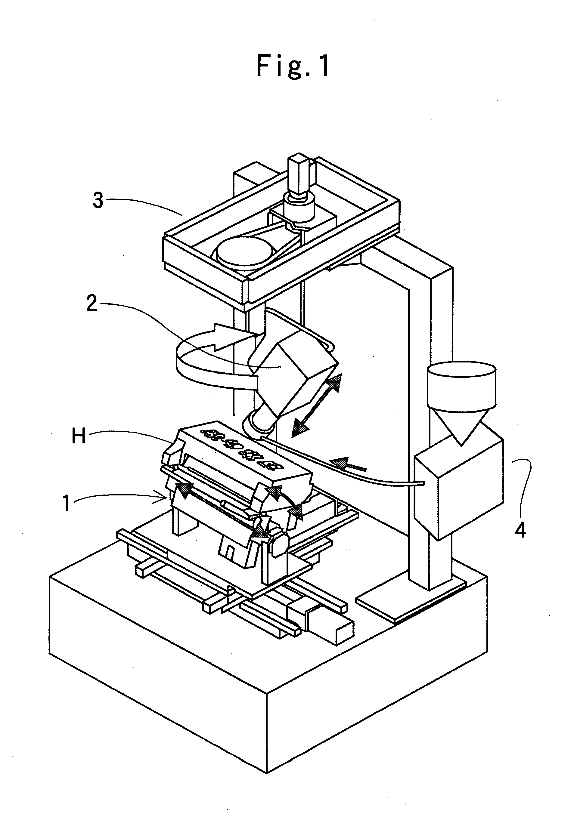
[0042] The entire constitution of a laser-clad processing apparatus of the present invention is shown in the perspective diagram of FIG. 1.

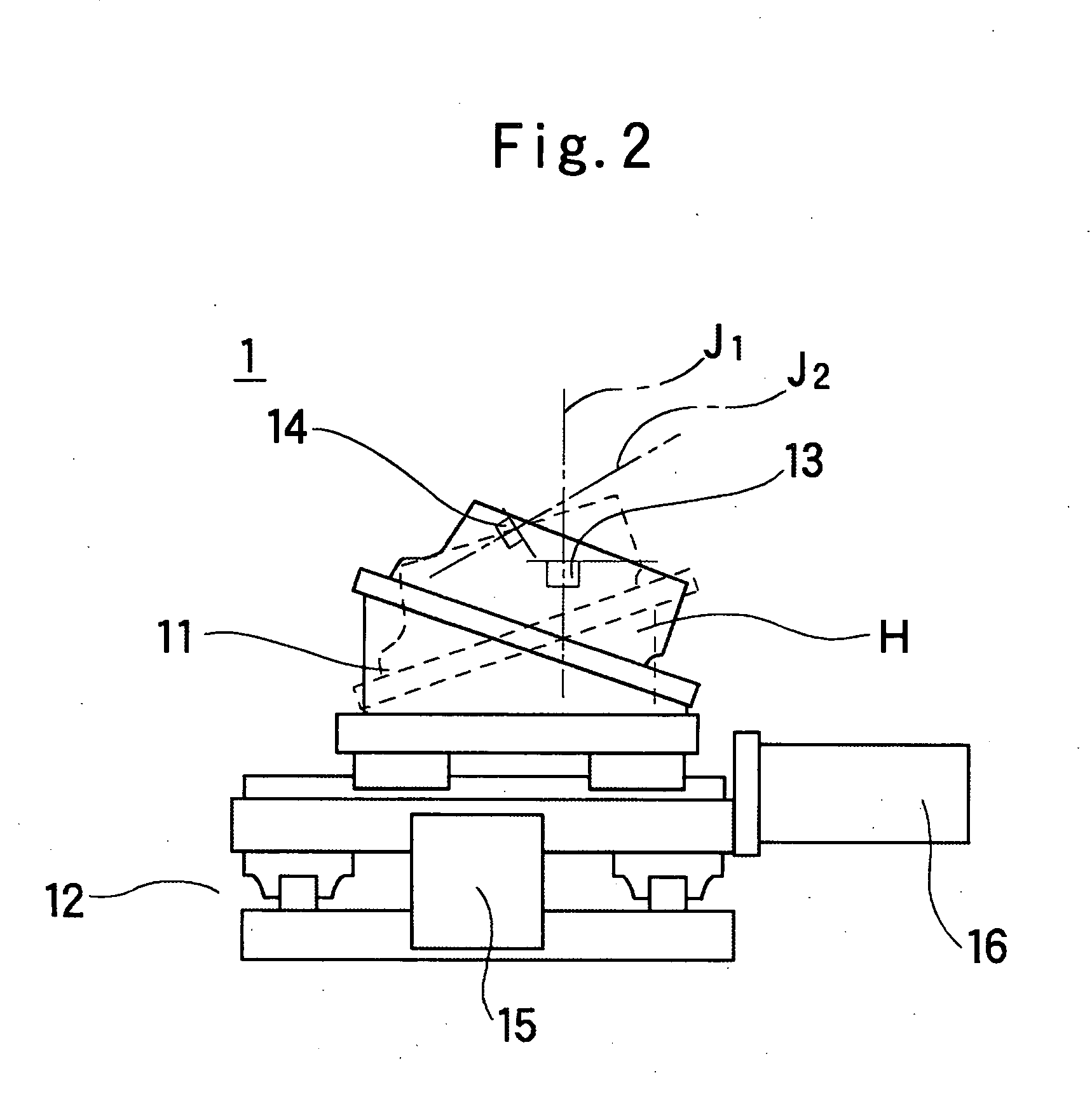
[0043] The laser-clad processing apparatus of the present invention is for carrying out laser-clad processing onto a valve-seat portion of a cylinder head H, and is constituted of cylinder-head holding means 1 for holding the cylinder head H in an inclining manner, a laser-processing head 2 for irradiating a laser beam onto a process part, and at the same time discharging a powdery material, rotary means 3 which rotates around the vertical line while holding the laser-processing head 2 inclinably to the vertical direction, and powdery-material supply means 4 for supplying the powdery material to the laser-processing head...


PUM

PropertyMeasurementUnit
Pressureaaaaaaaaaa
Diameteraaaaaaaaaa
Volumeaaaaaaaaaa

Abstract

A laser-clad processing apparatus of the present invention is one which is for carrying out laser-clad processing onto a valve-seat portion of a cylinder head, and is characterized in that it comprises cylinder-head holding means (1) for holding a cylinder head (H) in an inclining manner so that the central axial line of a valve seat becomes the vertical direction, a laser-processing head (2) for irradiating a laser beam onto a process part of the valve seat and at the same time discharging a powdery material to this process part, rotary means (3) which rotates around the central axial line of the valve seat in such a state that the laser-processing head is inclined with respect to the vertical direction, and powdery-material supply means (4) for supplying the powdery material to the laser-processing head.
Moreover, a laser-clad processing method of the present invention is characterized in that it fixes the cylinder head (H), and forms a clad layer while rotating the laser-processing head (2), which emits the laser beam with respect to the valve-seat portion of the cylinder head and discharges the powdery material, around the axial center line of the valve seat.

Description

TECHNICAL FIELD [0001] The present invention relates to a laser-clad processing apparatus for forming a clad layer on a valve-seat portion of a cylinder head by means of a laser beam and a laser-clad processing method therefor, more particularly, it relates to a laser-clad processing apparatus which fixes a cylinder head and forms a clad layer while rotating a laser-processing head, which emits a laser beam with respect to a valve-seat portion of the cylinder head and discharges a powder material, around the axial center line of the valve seat, and a laser-clad processing method therefor. BACKGROUND ART [0002] As for a conventional technique in regard to laser-clad processing, a laser-clad apparatus disclosed in Japanese Unexamined Patent Publication (KOKAI) No. 9-155,583 has been known, for example. The laser-clad apparatus disclosed in the publication is, as shown in FIG. 25, one which is equipped with laser-beam irradiation means 50 for irradiating a laser beam L with respect to ...

Claims


Application Information

Patent Timeline
IPC IPC(8): B23K26/34F01L3/24B23K26/10F02F1/24
CPCB23K26/103B23K26/34F01L3/04F01L2103/00B23K26/3226B23K35/0244B23K26/32B23K2103/10B23K2103/12B23K2103/18F01L2303/00
Inventor SATO, AKIOISHIKAWA, YOSHINORI
Owner TOYOTA JIDOSHA KK
Why Eureka
Try Eureka