Optical image stabilizer and a method of controlling the optical image stabilizer

a technology of optical image stabilizer and optical image, which is applied in the direction of electric controller, electric programme control, dynamo-electric converter control, etc., can solve the problem of greater power consumption of the stepping motor than that of the drive coil, and achieve the effect of less power consumption

Inactive Publication Date: 2006-08-03
HOYA CORP
View PDF26 Cites 13 Cited by
  • Summary
  • Abstract
  • Description
  • Claims
  • Application Information

AI Technical Summary

Benefits of technology

[0006] The present invention provides a low-power-consumption optical image stabilizer using at least one stepping motor as a drive source for moving an image-stabilizing optical element. The prevent invention further provides a method of controlling such an optical image stabilizer so as to consume less power.

Problems solved by technology

Nevertheless, the power consumption of the stepping motor tends to be greater than that of the drive coil during an image-stabilizing operation.

Method used


Image

  • Optical image stabilizer and a method of controlling the optical image stabilizer
  • Optical image stabilizer and a method of controlling the optical image stabilizer
  • Optical image stabilizer and a method of controlling the optical image stabilizer

Examples


Embodiment Construction

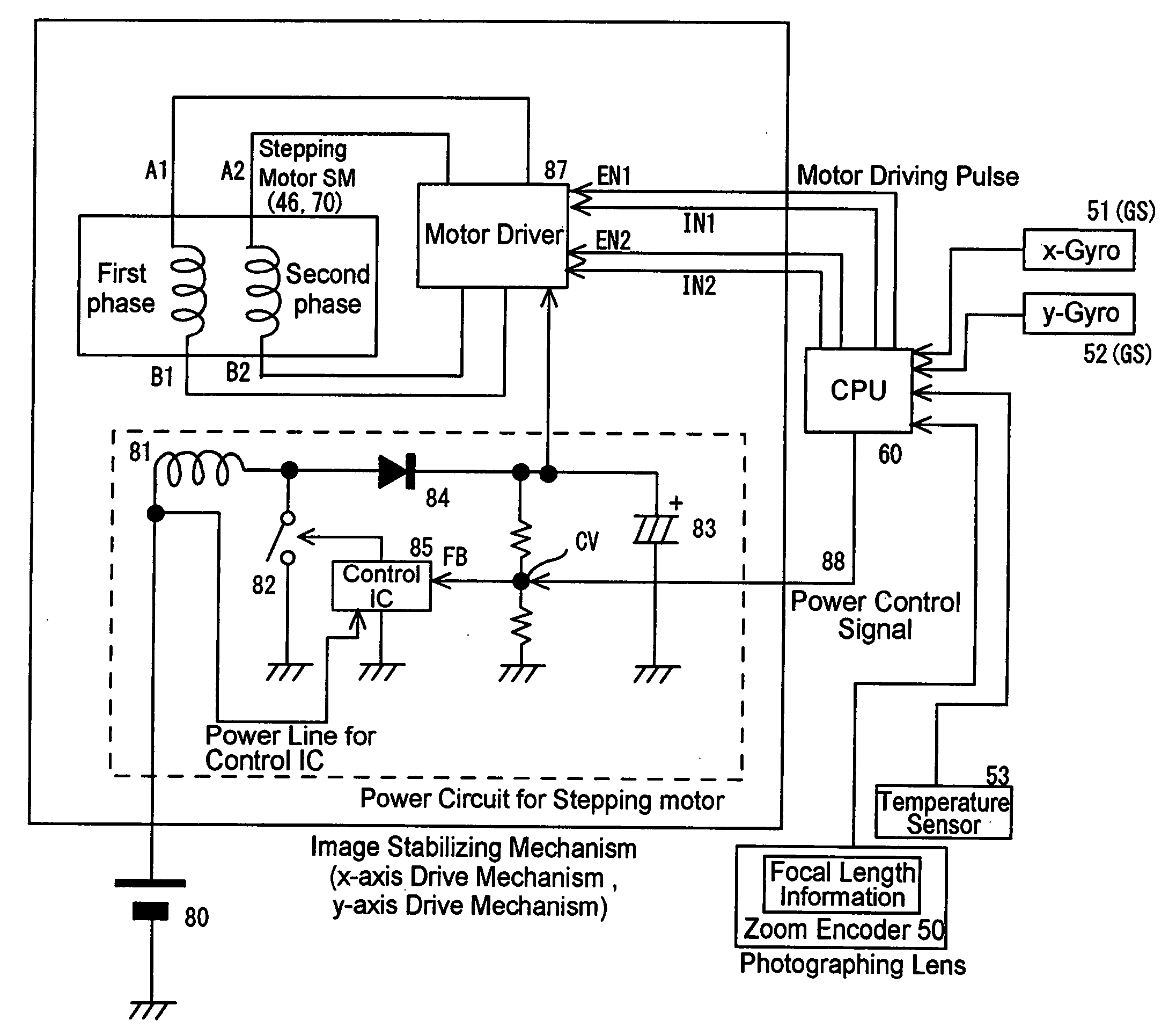
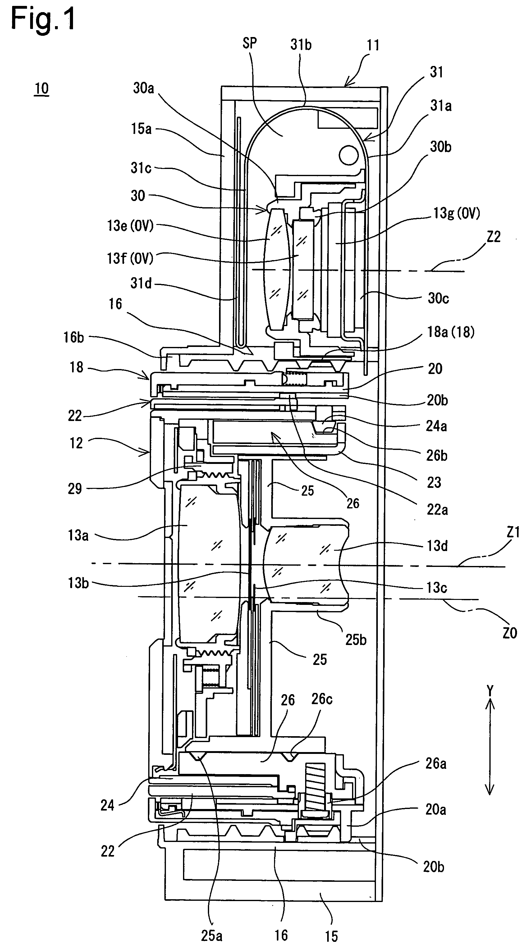
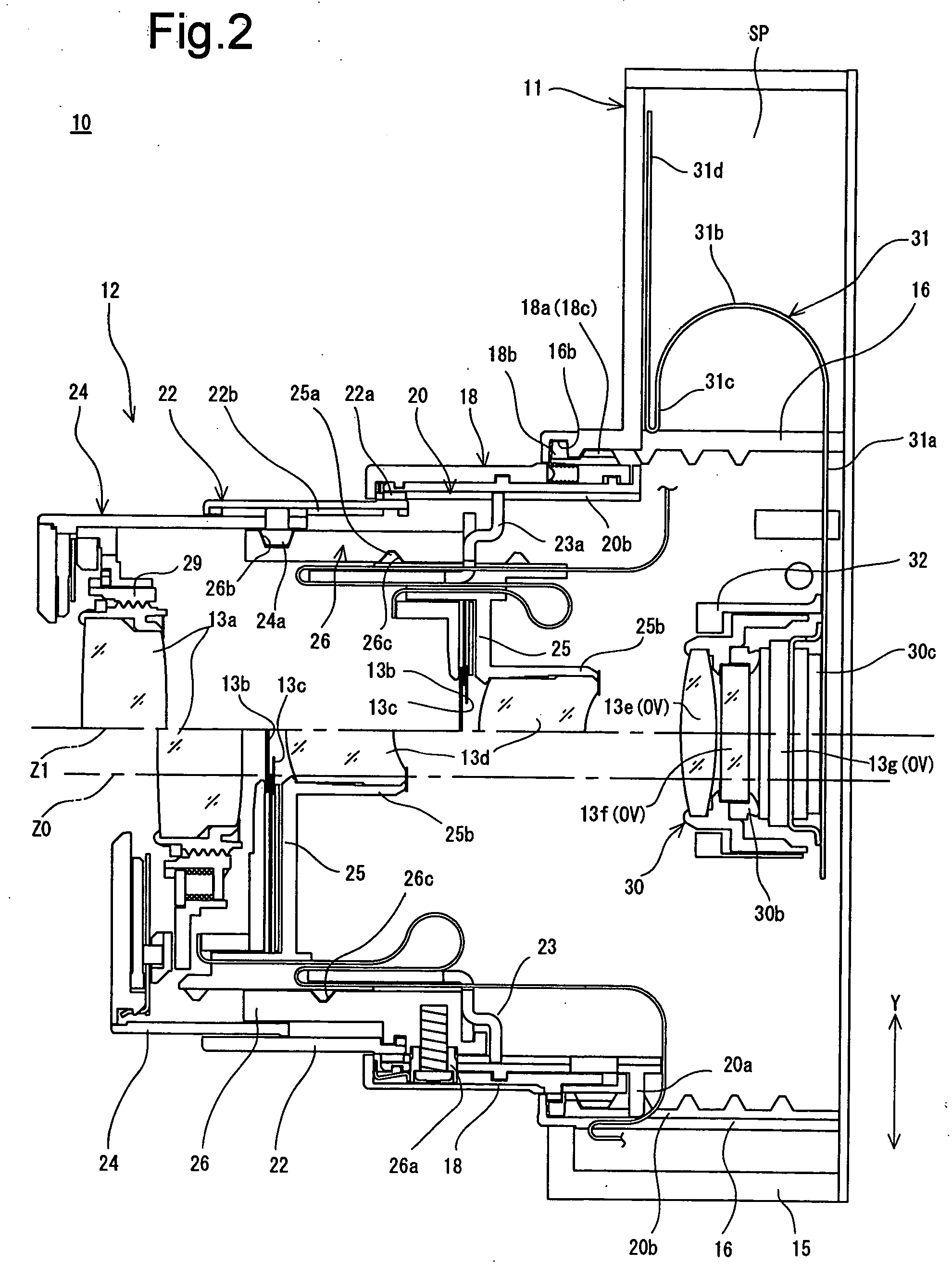
[0077]FIGS. 1 and 2 show cross-sections of a zoom lens 10 which is incorporated in a zoom lens camera. The zoom lens 10 is provided with a box-shaped housing 11 and a retractable barrel portion 12 retractably supported inside the housing 11. The outside of the housing 11 is covered by exterior components of the camera; the exterior components are not shown in the drawings. A photographing optical system of the zoom lens 10 includes a first lens group 13a, a shutter 13b, a diaphragm 13c, a second lens group 13d, a third lens group (radially-retractable optical element / image-stabilizing optical element) 13e, a low-pass filter (radially-retractable optical element / image-stabilizing optical element) 13f, and a CCD image sensor (radially-retractable optical element / image-stabilizing optical element) 13g (hereinafter referred to as a CCD), in that order from the object side (the left side as viewed in FIGS. 1 and 2). As shown in FIG. 5, the CCD 13g is electrically connected to an image pr...


PUM


Abstract

An optical image stabilizer includes an optical system including at least one image shake counteracting optical element movable in a plane orthogonal to an optical axis; at least one stepping motor for moving the image shake counteracting optical element in the plane; at least one shake velocity sensor which senses the speed of shake applied to the optical system; and a controller which calculates the number of driving pulses for the stepping motor based on shake speed information output from the shake velocity sensor, and drives the stepping motor so that the image shake counteracting optical element moves in the plane to counteract image shake on an imaging surface of the optical system. The controller changes power supplied to the stepping motor in accordance with the shake speed information when driving the stepping motor.

Description

BACKGROUND OF THE INVENTION [0001] 1. Field of the Invention [0002] The present invention relates to an optical image stabilizer for an optical instrument and a method of controlling an optical image stabilizer incorporated in an optical instrument. [0003] 2. Description of the Related Art [0004] This type of optical image stabilizer for an optical instrument typically operates to stabilize an object image on an imaging surface (imaging plane) by moving a part of an optical system of the optical instrument relative to the optical axis of the optical system in accordance with vibrations applied to the body of the optical instrument, and has often been incorporated especially in a digital camera or a pair of binoculars in recent years. [0005] In a mobile optical instrument such as digital camera and binoculars, there has been a strong demand for an extension of a battery lifetime. Accordingly, there has been a demand for a reduction of power consumption of even the optical image stabi...

Claims


Application Information

Patent Timeline
Patent Type & Authority Applications(United States)
IPC IPC(8): G05B19/40
CPCG02B27/646H04N5/2251H04N5/2253H04N5/2254H04N5/23248H04N5/23287H04N23/54H04N23/55H04N23/651H04N23/68H04N23/687G02B27/64G05B11/01G05B11/011G05D19/02H02P8/18H02P8/00
Inventor NOMURA, HIROSHIKAKIUCHI, SHINICHI
Owner HOYA CORP
Why Eureka
Try Eureka