Use of free-space coupling between laser assembly, optical probe head assembly, spectrometer assembly and/or other optical elements for portable optical applications such as Raman instruments

Inactive Publication Date: 2006-08-03
AHURA CORP
View PDF33 Cites 38 Cited by
  • Summary
  • Abstract
  • Description
  • Claims
  • Application Information

AI Technical Summary

Benefits of technology

[0016] Accordingly, a primary object of the present invention is to provide a novel arrangement for coupling together the va

Problems solved by technology

Such fiber couplings have the disadvantage of increasing the size of the Raman instrument.
This is because such fiber couplings require certain space considerations, e.g., connectors at both ends of the fiber, constraints on how tightly the fiber can be curved, etc.
In addition to the foregoing, the use of fiber couplings between the optical elements introduces a significant power loss to the optical circuit, which in turn requires the use of a more powerful laser, which in turn increases the Raman analyzer's power requirements, which in turn increases the

Method used


Image

  • Use of free-space coupling between laser assembly, optical probe head assembly, spectrometer assembly and/or other optical elements for portable optical applications such as Raman instruments
  • Use of free-space coupling between laser assembly, optical probe head assembly, spectrometer assembly and/or other optical elements for portable optical applications such as Raman instruments
  • Use of free-space coupling between laser assembly, optical probe head assembly, spectrometer assembly and/or other optical elements for portable optical applications such as Raman instruments

Examples


Embodiment Construction

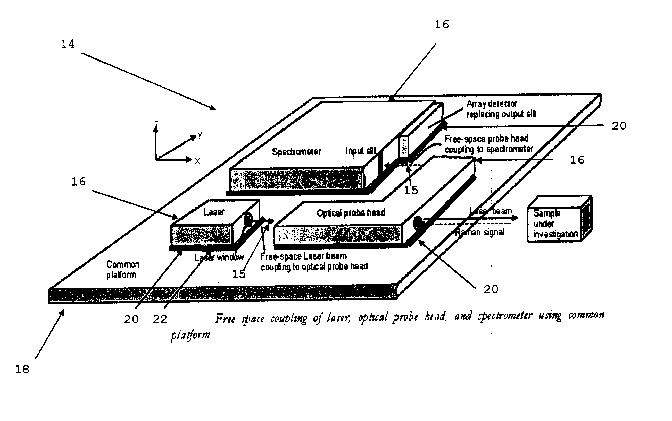
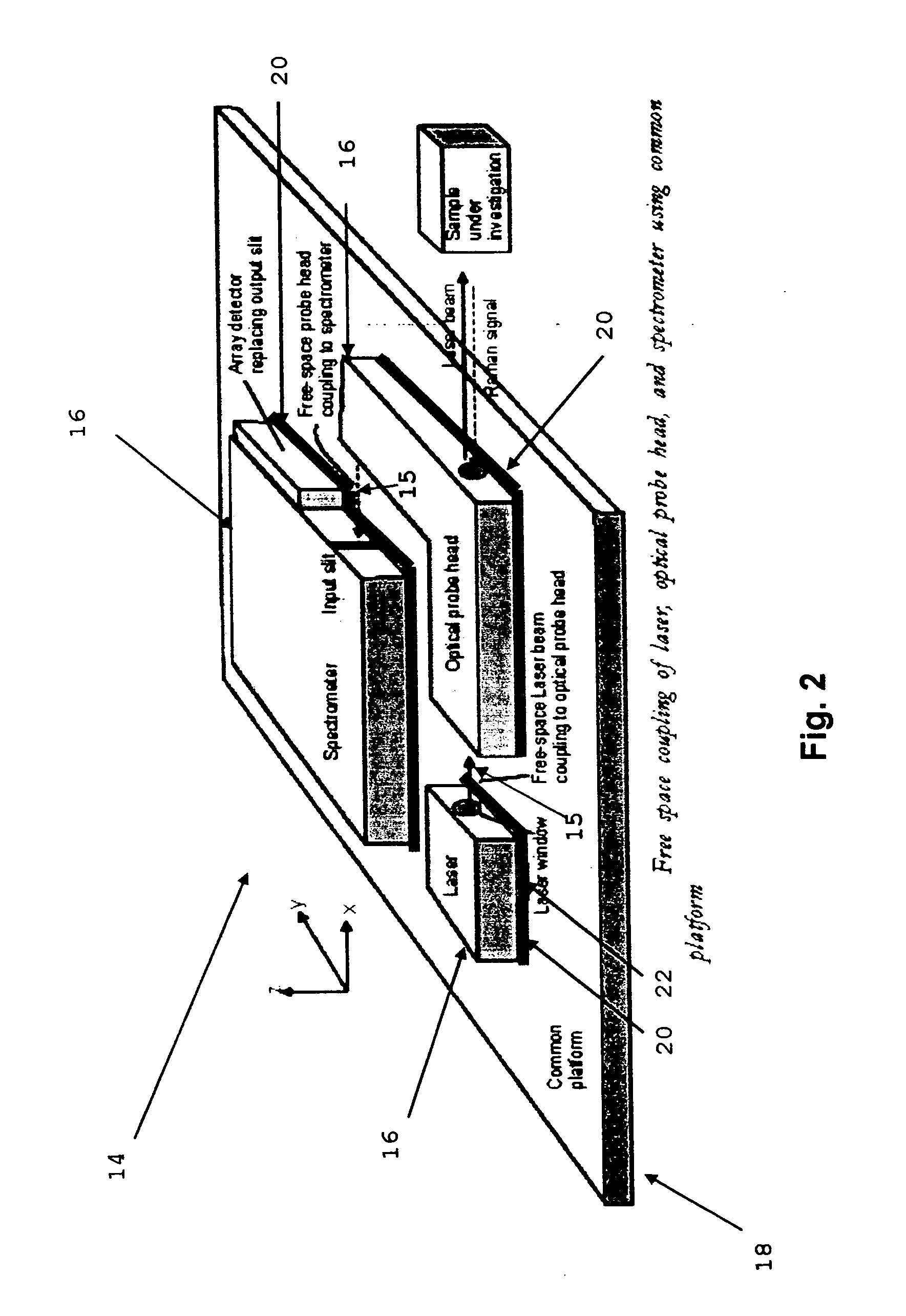
[0118] Looking next at FIG. 2, there is shown a novel optical circuit 14 in which free-space coupling 15 is provided between the basic optical elements 16 (e.g., laser assembly, optical probe head assembly, spectrometer assembly, etc.) so as to achieve a compact optical circuit. This is done by mounting the various optical elements 16 on a common platform 18 which is sufficiently mechanically robust as to maintain the free-space optical coupling 15 between the various optical elements 16. The use of free-space optical coupling 15 between the various optical elements 16 permits a more compact optical circuit, since the space requirements of optical fibers can be eliminated.

[0119] This approach can be applied to any portable instruments that use two or more optical elements. For example, it can be used with the various optical elements of Raman spectrometer assemblies (i.e., laser assemblies, optical probe head assemblies, spectrometer assemblies, etc.). It can also be used with othe...


PUM


Abstract

A compact, lightweight, portable optical assembly comprising: a platform; and a plurality of optical elements mounted to the platform; wherein the plurality of optical elements are optically connected to one another with free-space couplings so as to form an optical circuit; and further wherein the platform is sufficiently mechanically robust so as to maintain the free-space optical coupling between the various optical elements. A method for making a compact, lightweight, portable optical assembly, comprising: providing a platform; and mounting a plurality of optical elements to the platform; wherein the plurality of optical elements are mounted to the platform so that they are optically connected to one another with free-space couplings so as to form an optical circuit; and further wherein the platform is sufficiently mechanically robust so as to maintain the free-space optical coupling between the various optical elements.

Description

REFERENCE TO PENDING PRIOR PATENT APPLICATIONS [0001] This patent application: [0002] (i) is a continuation-in-part of pending prior U.S. patent application Ser. No. 11 / 117,940, filed Apr. 29, 2005 by Peidong Wang et al. for METHOD AND APPARATUS FOR CONDUCTING RAMAN SPECTROSCOPY (Attorney's Docket No. AHURA-2230); [0003] (ii) is a continuation-in-part of pending prior U.S. patent application Ser. No. 11 / 119,076, filed Apr. 29, 2005 by Daryoosh Vakhshoori et al. for EXTERNAL CAVITY WAVELENGTH STABILIZED RAMAN LASERS INSENSITIVE TO TEMPERATURE AND / OR EXTERNAL MECHANICAL STRESSES, AND RAMAN ANALYZER UTILIZING THE SAME (Attorney's Docket No. AHURA-24); [0004] (iii) is a continuation-in-part of pending prior U.S. patent application Ser. No. 11 / 119,139, filed Apr. 30, 2005 by Daryoosh Vakhshoori et al. for LOW PROFILE SPECTROMETER AND RAMAN ANALYZER UTILIZING THE SAME (Attorney's Docket No. AHURA-26); [0005] (iv) is a continuation-in-part of pending prior U.S. patent application Ser. No. ...

Claims


Application Information

Patent Timeline
IPC IPC(8): G01J3/44G01N21/65
CPCG01J3/0256G01J3/0272G01J3/0286G01J3/0291G01J3/44G01N21/65G01N2021/656G01N2201/0221
Inventor VAKHSHOORI, DARYOOSHCHEN, PEILIAZIMI, MASUDWANG, PEIDONGSHEN, YUKNOPP, KEVIN J.ZHU, LEYUNBROWN, CHRISTOPHER D.VANDER RHODES, GREGORY H.
Owner AHURA CORP
Why Eureka
Try Eureka