Magnetic recording head having solenoidal coil

a technology of solenoids and recording heads, which is applied in the field of magnetic recording heads, can solve the problems of difficult to reduce the size and manufacturing cost of the apparatus, serious phenomena, and complication of the apparatus

Inactive Publication Date: 2006-08-03
TDK CORPARATION
View PDF7 Cites 1 Cited by
  • Summary
  • Abstract
  • Description
  • Claims
  • Application Information

AI Technical Summary

Benefits of technology

[0021] The present invention is intended to solve the above problems. It is an object of the present invention to provide a magnetic head including a main magnetic pole layer prevented from unintended writing during non-recording.
[0024] Even if the magnetization of the first magnetic layer is directed perpendicularly to the opposed face when the magnetic head is put into a non-recording mode by stopping the supply of a current to the coil layer, a magnetic field emanating from the front end face of the first magnetic layer to outside the magnetic head can be prevented from being generated. This is because, a magnetic circuit including the first magnetic layer, the switching layer, and the second magnetic layer is formed by rendering the switching layer magnetic. Therefore, unintended data can be prevented from being written on the recording medium during non-recording.
[0025] In the magnetic head, the first magnetic layer magnetized perpendicularly to the opposed faces is not magnetized in parallel thereto. The magnetic head has a mechanism for creating the magnetic circuit in the magnetic head to prevent a magnetic field from emanating from the magnetic head. Therefore, the magnetic head requires a smaller amount of energy as compared to known magnetic heads. If the first magnetic layer is reduced in size in the track width direction so as to cope with an increase in recording density, any unintended signal can be securely prevented from being written on the recording medium during non-recording.
[0029] If the switching layer, the first magnetic layer, the second magnetic layer are directly connected to each other, a magnetic flux can be readily confined in the magnetic head. This is because the magnetic circuit including the first magnetic layer, the switching layer, and the second magnetic layer has low magnetic resistance when the switching layer becomes magnetic. If the insulating layers are each disposed between the switching layer and the first or second magnetic layer, the heat conduction between these layers can be reduced.
[0030] In the magnetic head, the front end face of the switching layer is preferably located close to the opposed faces and spaced from the opposed faces in the height direction. Therefore, a magnetic field can be prevented from being generated outside the magnetic head during non-recording.
[0034] In the magnetic head, the switching layer is disposed in the space between the first and second magnetic layers. When the switching layer is rendered non-magnetic during recording with the magnetic head, the magnetization of the first magnetic layer is directed perpendicularly to the opposed faces and a magnetic field emanating from the front end face of the first magnetic layer to the recording medium is generated, whereby a magnetic recording signal is written on the recording medium. Even if the magnetization of the first magnetic layer is directed perpendicularly to the opposed face when the magnetic head is put into a non-recording mode by stopping the supply of a current to the coil layer, a magnetic field emanating from the front end face of the first magnetic layer to outside the magnetic head can be prevented from being generated. This is because, a magnetic circuit including the first magnetic layer, the switching layer, and the second magnetic layer is formed by rendering the switching layer magnetic. Therefore, unintended data can be prevented from being written on the recording medium during non-recording.

Problems solved by technology

This causes an unintended signal to be written on the recording medium M. A reduction in the size of the main magnetic pole layer 10 and a reduction in track width cause this phenomenon to be serious.
This causes a complication in the apparatus.
Therefore, it is difficult to reduce the size and manufacturing cost of the apparatus.
This leads to difficulty in controlling the magnetic domains present in the end portions of the main magnetic pole layer.

Method used


Image

  • Magnetic recording head having solenoidal coil
  • Magnetic recording head having solenoidal coil
  • Magnetic recording head having solenoidal coil

Examples


first embodiment

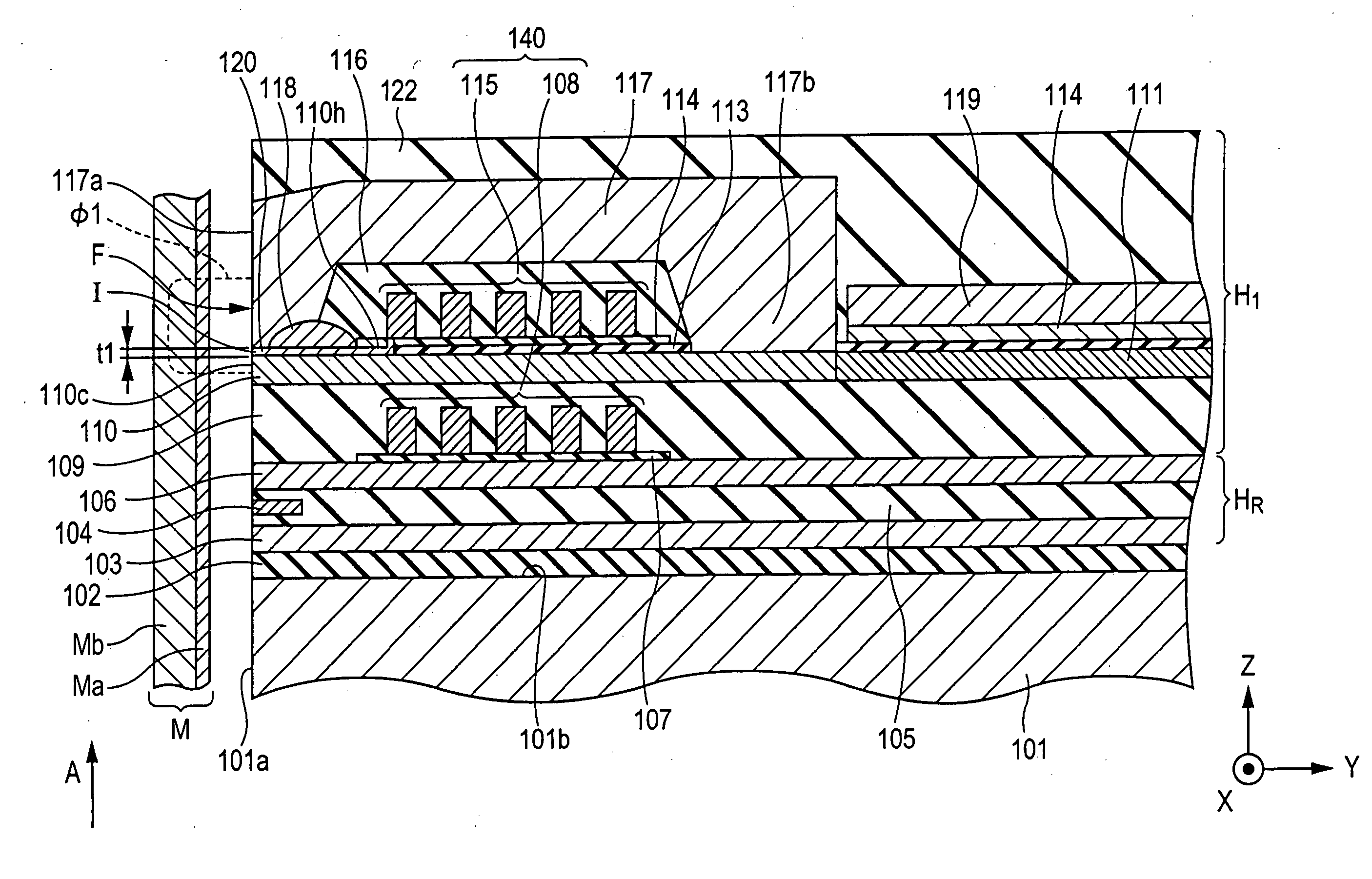
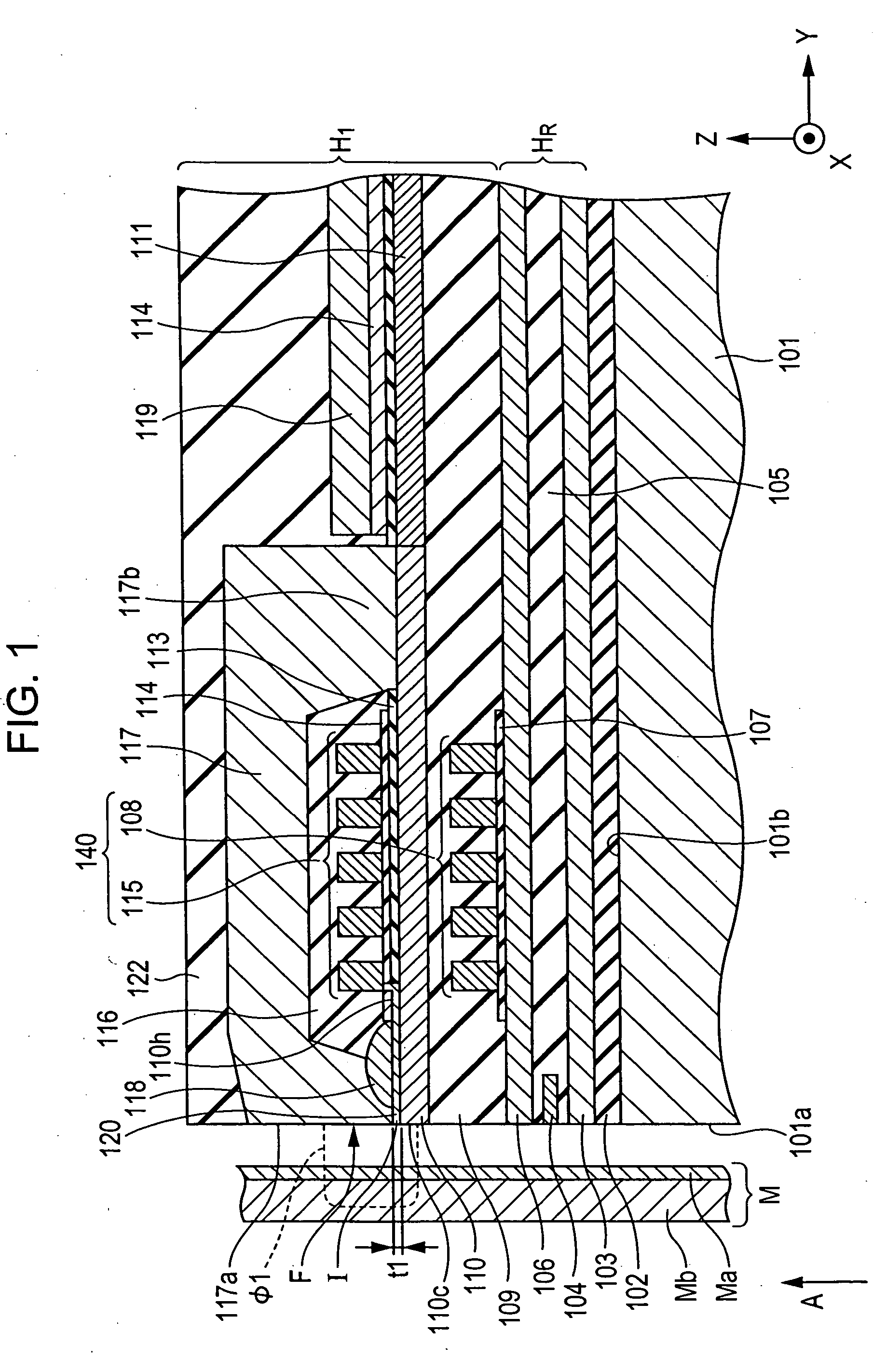
[0049]FIG. 1 is a vertical sectional view of a magnetic head according to the present invention. The magnetic head is represented by reference numeral H1 in FIG. 1 and is a type of perpendicular recording magnetic head for applying a magnetic field perpendicular to a recording medium M to perpendicularly magnetize a hard layer Ma included in the recording medium M. The magnetic head H1 has an opposed face H1a opposed to the recording medium M.

[0050] The recording medium M has, for example, a disc shape, further includes a soft layer Mb, and rotates on its center axis. The hard layer Ma is located close to the magnetic head H1 and has high coercive force. The soft layer Mb is located far from the magnetic head H1 and has high magnetic permeability.

[0051] A slider 101 is made of a non-magnetic material such as Al2O3—TiC and has an opposed end face 101a opposed to the recording medium M. The rotation of the recording medium M creates an air flow, which separates the recording medium M...

second embodiment

[0076] In the magnetic head H1, the switching layer 120 is connected to the first coil layers 115 and heated by heat generated from the first coil layers 115. However, the switching layer 120 need not be necessarily connected to the first coil layers 115 directly and a portion of the switching layer 120 may be located close to the first coil layers 115 such that Joule heat generated from the first coil layers 115 is conducted to the switching layer 120. FIG. 5 shows a magnetic head according to the present invention. This magnetic head has a face opposed to a recording medium and includes a switching layer 120 extending from the opposed face in a height direction (the Y direction in FIG. 5), an insulating layer 114, and first coil layers 115, these layers being arranged in that order. Joule heat generated from these first coil layers 115 can be conducted to this switching layer 120 during recording by adjusting the thickness of this insulating layer 114. Therefore, this switching la...

third embodiment

[0077]FIG. 6 shows a magnetic head according to the present invention. This magnetic head has a face opposed to a recording medium and includes first coil layers 115, a switching layer 120, an insulating layer 113 (see FIG. 7), and a heater layer 123 which is spaced from these first coil layers 115 and which is located close to this switching layer 120. FIG. 7 is an enlarged fragmentary sectional view showing the periphery of the opposed face of this magnetic head. With reference to FIG. 7, this switching layer 120, this insulating layer 113, and this heater layer 123 are arranged in the Y direction in that order. This heater layer 123 is made of a conductive material such as Cu, Ni—Cu, Ni—Cr, Ta, or W. During recording with the magnetic head, a current is supplied to this heater layer 123 simultaneously with the supply of a current to these first coil layers 115. This allows this switching layer 120 to be heated to a temperature higher than its Curie temperature, whereby this switc...


PUM

PropertyMeasurementUnit
temperatureaaaaaaaaaa
thicknessaaaaaaaaaa
temperatureaaaaaaaaaa

Abstract

A magnetic head includes a first magnetic layer in which a face, opposed to a recording medium, having a size equal to a track width in a track width direction; a second magnetic layer in which a face, opposed to the recording medium, having a size greater than the track width in the track width direction, the first and second magnetic layers being spaced from each other in an element thickness direction, the first and second magnetic layers being connected to each other at a region located in a height direction; and a coil layer, located far from the opposed faces, for applying recording magnetic fields to the first and second magnetic layers such that magnetic data is recorded on the recording medium with a perpendicular magnetic field concentrated on the first magnetic layer.

Description

BACKGROUND OF THE INVENTION [0001] 1. Field of the Invention [0002] The present invention relates to magnetic heads for recording signals by applying magnetic fields perpendicular to recording media such as discs including hard layers. The present invention particularly relates to a magnetic head prevented from writing data on a recording medium during non-recording. [0003] 2. Description of the Related Art [0004]FIG. 13 is a vertical sectional view of a known magnetic head H1. The magnetic head H1 is a type of perpendicular recording magnetic head for applying a magnetic field perpendicular to a recording medium M to perpendicularly magnetize a hard layer Ma included in the recording medium M. The magnetic head H1 has an opposed face opposed H1a to the recording medium M. [0005] The recording medium M has, for example, a disc shape, further includes a soft layer Mb, and rotates on its center axis. The hard layer Ma is located far from the magnetic head H1 and has high coercive forc...

Claims


Application Information

Patent Timeline
Patent Type & Authority Applications(United States)
IPC IPC(8): G11B5/147
CPCG11B5/1278G11B5/3116G11B5/3146
Inventor YAZAWA, HISAYUKI
Owner TDK CORPARATION
Why Eureka
Try Eureka