Hydrodynamic thrust bearing assembly

a technology of thrust bearings and bearing assemblies, which is applied in the direction of bearings, shafts and bearings, rotary bearings, etc., can solve the problems of premature bearing failure, significant component of the cost of drilling a well, and the stress of bearing contact reaching extremely high levels, so as to achieve reliable and economical effects

Inactive Publication Date: 2006-08-03
KALSI ENG
View PDF48 Cites 23 Cited by
  • Summary
  • Abstract
  • Description
  • Claims
  • Application Information

AI Technical Summary

Benefits of technology

[0012] It is an objective of the present invention to provide a reliable, economical, impact resistant thrust bearing for use in mechanical equipmen

Problems solved by technology

Relative to their small size, these bearings are severely loaded, and the bearing contact stresses reach extremely high levels, especially during severe impact loading.
The races of roller thrust bearings are subject to Brinnelling-type damage from the high impact forces that are encountered in drilling operations, which can lead to premature bearing failure.
The downtime associated with the lengthy round trips required

Method used


Image

  • Hydrodynamic thrust bearing assembly
  • Hydrodynamic thrust bearing assembly
  • Hydrodynamic thrust bearing assembly

Examples


Embodiment Construction

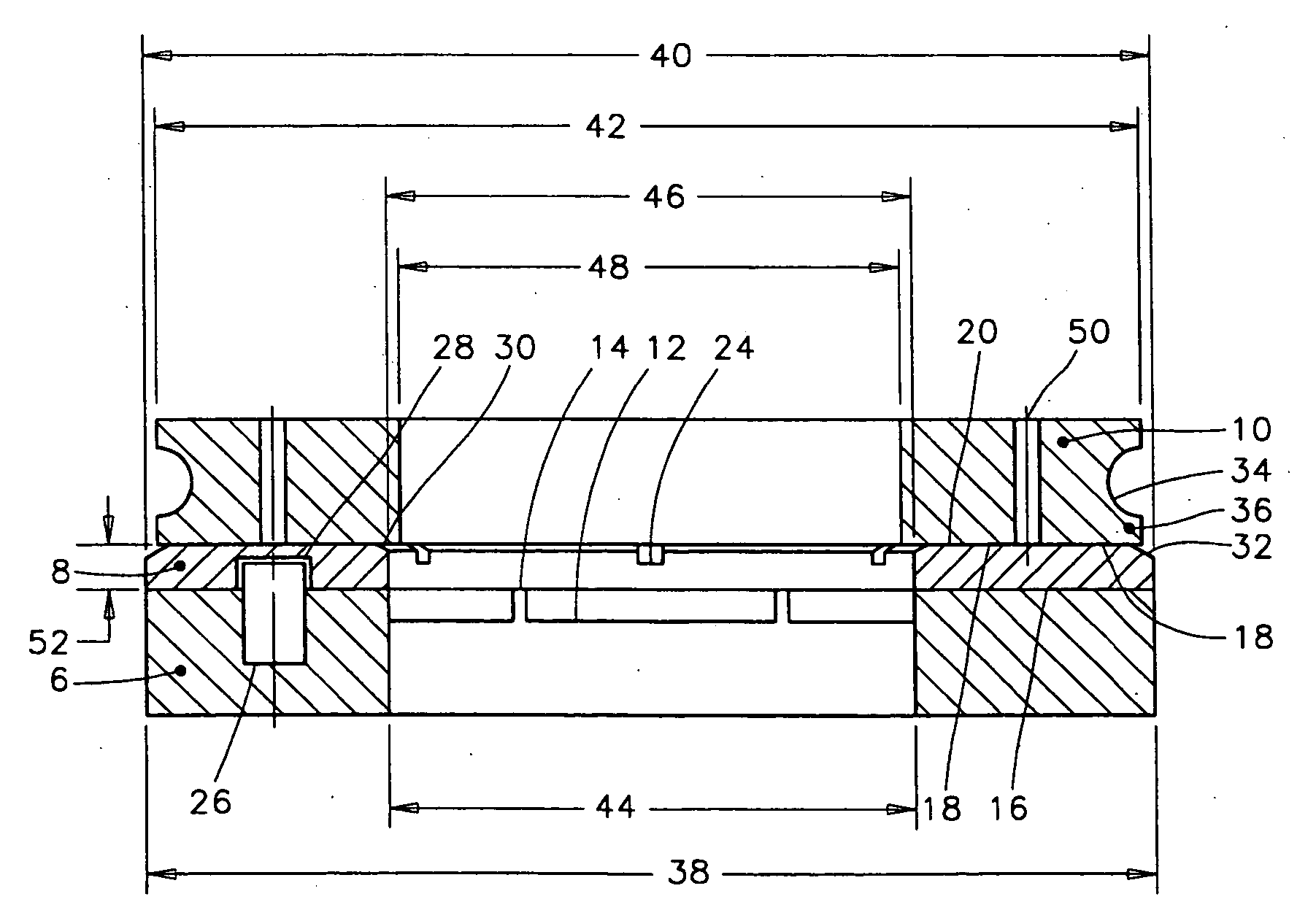
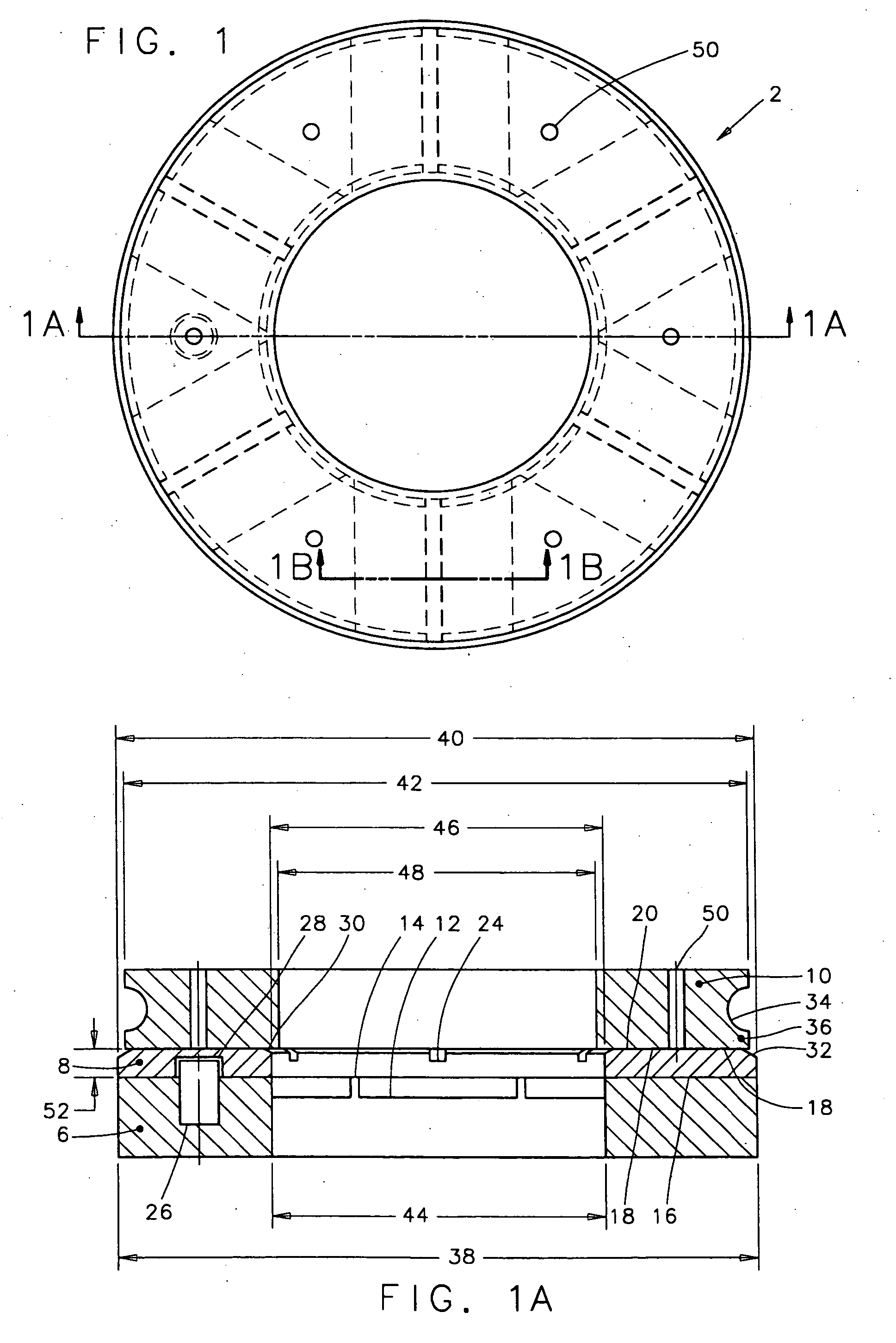
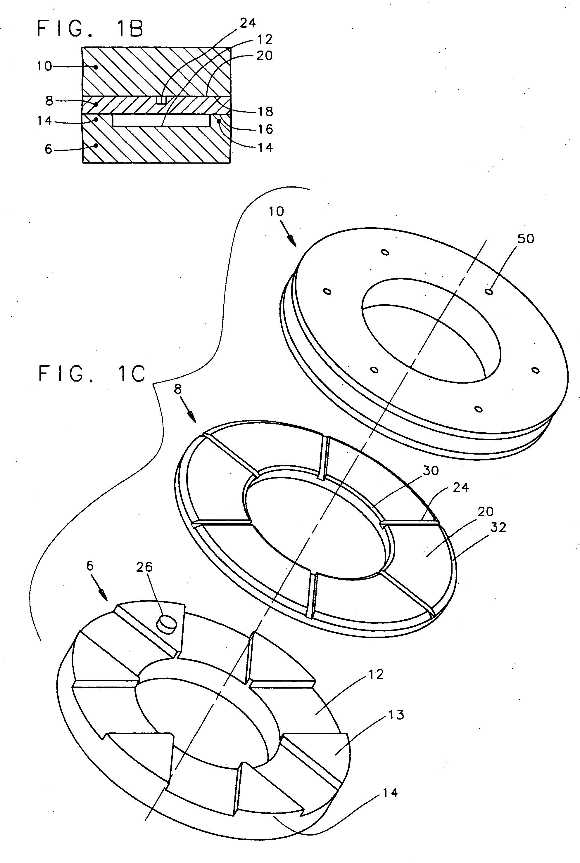
[0033] The preferred embodiment of the thrust bearing assembly according to the present invention is generally referenced in FIG. 1 as reference numeral 2. FIGS. 1-1D illustrate a preferred embodiment of the hydrodynamic thrust bearing assembly 2 of present invention. With reference to FIG. 2A, one of the primary purposes of the thrust bearing assembly 2 of the present invention is to transfer a thrust load between one member, such as a housing H, and another member, such as a shaft S, of a machine where the housing H and the shaft S are relatively rotatable with respect to one another.

[0034] The preferred embodiment of the thrust bearing assembly 2 comprises three principal components: a support structure 6, a thrust washer 8, and a dynamic race 10. The thrust washer 8 is sandwiched between the support structure 6 and the dynamic race 10. Preferably, the thrust washer 8 has a dynamic washer surface 20 of substantially planar configuration and a static washer surface 16 that contac...


PUM


Abstract

A thrust bearing assembly including a ring-like support structure having a castellated end configuration, a ring-like dynamic race, and a ring-like thrust washer sandwiched between the castellated end configuration and the dynamic race. The castellated end configuration defines a plurality of support regions and a plurality of notches between adjacent support regions. The thrust washer sits atop the castellations of the support structure. The castellated end configuration of the support structure provides intermittent support regions and intermittent unsupported regions to the thrust washer. When a thrust load is applied to the bearing assembly, the thrust washer elastically flexes at the unsupported regions and creates undulations in the washer's dynamic surface to create an initial hydrodynamic fluid wedge with respect to a mating surface of the dynamic race. The gradually converging geometry created by these undulations promotes a strong hydrodynamic action that wedges a lubricant film of a predictable magnitude into the dynamic interface between the thrust washer and the dynamic race in response to relative rotation. This lubricant film physically separates the dynamic surfaces of the thrust washer and dynamic race from each other, thus minimizing asperity contact, and reducing friction, wear and bearing-generated heat, while permitting operation at higher load and speed combinations.

Description

CROSS-REFERENCE TO RELATED APPLICATIONS [0001] This application claims the benefit of U.S. Provisional Application Ser. No. 60 / 649,498, filed Feb. 4, 2005, and entitled “Sealed Bearing Assembly”.BACKGROUND OF THE INVENTION [0002] 1. Field of the Invention [0003] The present invention relates generally to thrust bearing assemblies, and more particularly to thrust bearing assemblies providing hydrodynamic lubrication of the loaded bearing surfaces in response to relative rotation. [0004] 2. Description of the Related Art [0005] Rotary drilling techniques are used to penetrate into the earth to create wells for obtaining oil and gas. In order to drill through the rock that is encountered in such endeavors, a drill bit is employed at the bottom of a hollow drill string. [0006] In many cases, rotary motion is imparted to the drill bit by a downhole mud motor that employs a sealed bearing assembly containing thrust and radial bearings that guide the rotation of the drill bit, and transfer...

Claims


Application Information

Patent Timeline
IPC IPC(8): F16C32/06
CPCF16C17/065F16C33/102F16C33/108
Inventor RICHIE, AARON P.KALSI, MANMOHAN S.
Owner KALSI ENG
Why Eureka
Try Eureka