Isolation damper pulley and method of producing the same

Active Publication Date: 2006-08-03
FUKOKU CO LTD
View PDF3 Cites 38 Cited by
  • Summary
  • Abstract
  • Description
  • Claims
  • Application Information

AI Technical Summary

Benefits of technology

[0030] Since the damper section and the isolation pulley section are assembled by fitting them, they can be assembled without welding these members, so that com

Problems solved by technology

Accordingly, a problem arises such that correcting work

Method used


Image

  • Isolation damper pulley and method of producing the same
  • Isolation damper pulley and method of producing the same
  • Isolation damper pulley and method of producing the same

Examples


Embodiment Construction

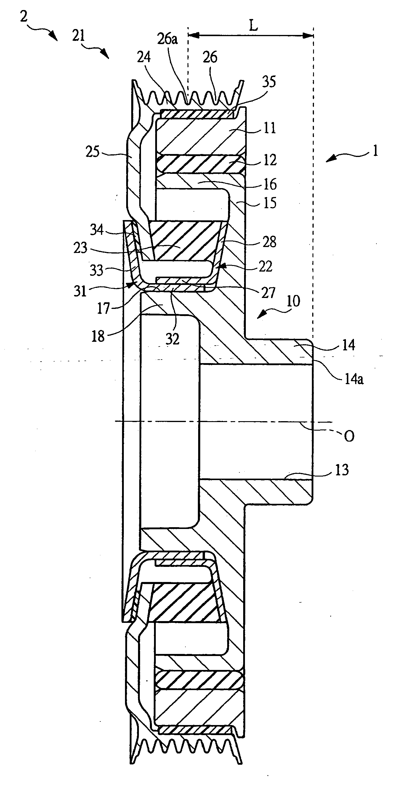
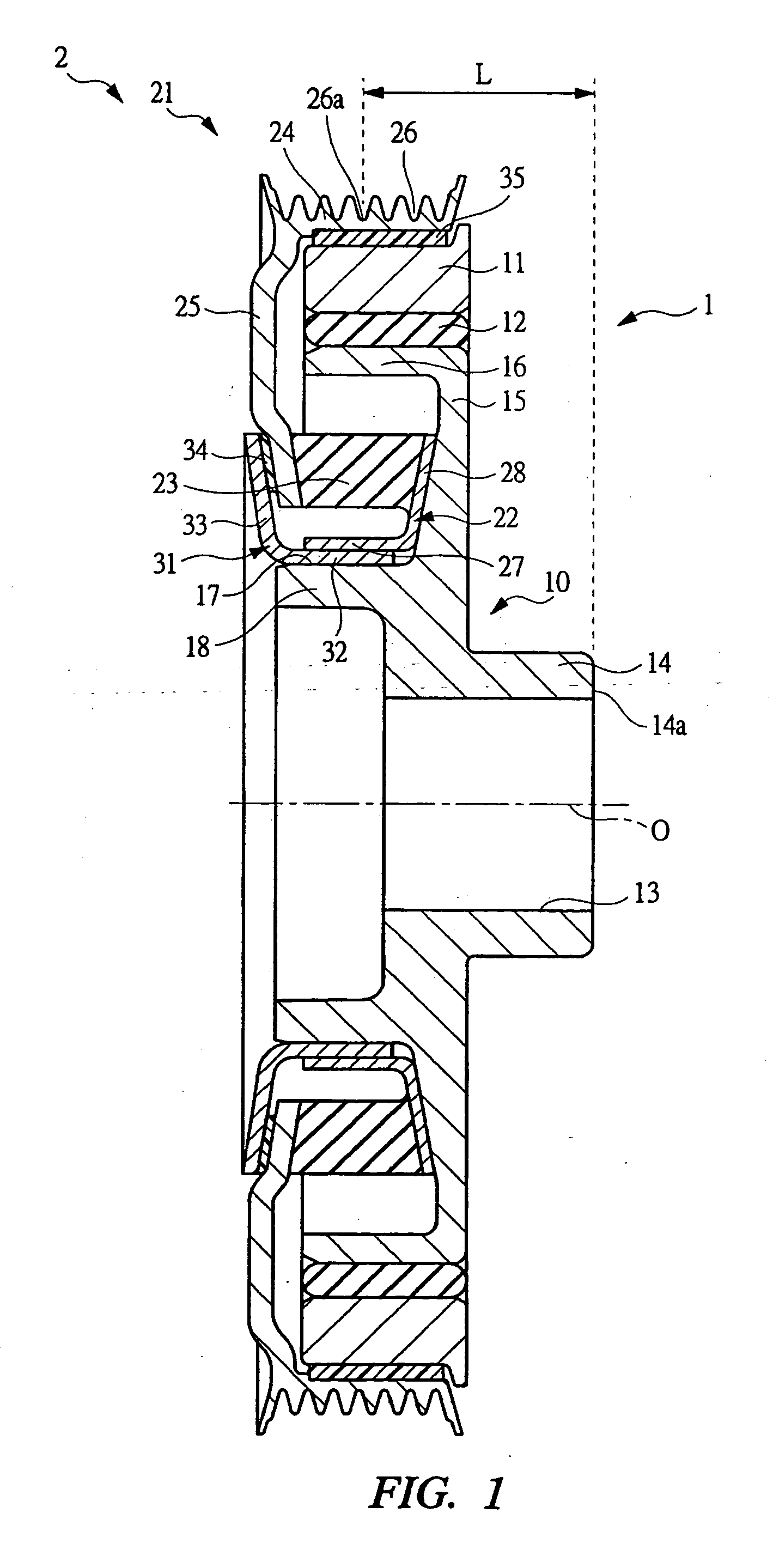
[0036] As shown in FIG. 1, an isolation damper pulley according to the present invention comprises a damper section 1 and an isolation pulley section 2, wherein the damper section 1 constitutes a damper unit and the isolation pulley section 2 constitutes a pulley unit. The damper section 1 includes a hub 10, an annular mass body 11, and an annular elastic member 12, thereby having a function of reducing a torsional vibration of a crankshaft.

[0037] The hub 10 includes: a boss portion 14 having a through hole 13 in which the crankshaft (not shown) is assembled; a disk portion 15 extending radially from the boss portion 14; and an outside cylindrical portion 16 extending axially from a peripheral edge of the disk portion 15 and having an outer circumferential surface 17 concentric with a center axis “O” of the boss portion 14, wherein an inside cylindrical portion 18 having an outer circumferential surface 17 concentric with the center axis O is provided to the disk portion 15 so as t...


PUM


Abstract

An isolation damper pulley comprises a damper section 1 and an isolation pulley section 2 assembled thereto, wherein a first fitting portion 18 constituted from a cylindrical portion concentric with a center axis O of a through hole 13 is provided to a hub 10 of the damper unit 1. The isolation pulley section 2 has a supporting member 22 fixed to a pulley portion 21 via an annular elastic member 23, wherein a second fitting portion 27 concentric with the first fitting portion 18 is provided to the supporting member 22. A third fitting portion 32 concentric with the first fitting portion 18 is provided to a pressing member 31 applying a precompression to the annular elastic member 23 in cooperation with the supporting member 22. The second fitting portion 27 and the third fitting portion 32 are fitted to each other and these fitting portions are fitted to the first fitting portion 18, so that the isolation pulley section 2 is assembled to the damper section 1.

Description

CROSS REFERENCE TO RELATED APPLICATIONS [0001] This application is entitled to the benefit of and incorporates by reference essential subject matter disclosed in International Patent Application No. PCT / JP2004 / 010156 filed on Jul. 9, 2004 and Japanese Patent Application No. 2003-293972 filed Jul. 11, 2003. TECHNICAL FILED [0002] The present invention relates to a technique for an isolation damper pulley, which is mounted on a crankshaft of an engine to transmit torque of the crankshaft to various auxiliary machines via an endless belt, and in particular to a technique for an isolation damper pulley, which cuts off a speed fluctuation of the crankshaft generated due to a torque fluctuation of the engine mainly during a low-speed revolution of the engine such as during an idling revolution of the engine and reduces a torsional vibration of the crankshaft. BACKGROUND ART [0003] As described in Japanese Patent Laid-open Publication No. 2001-159448, for example, an isolation damper pulle...

Claims


Application Information

Patent Timeline
IPC IPC(8): F16H55/36F16D3/00F16F15/126F16F15/14
CPCF16F15/126F16F15/1442F16H55/36F16H2055/366F16F15/10
Inventor WATANABE, HIDEAKIOKI, KAZUMIKAKINUMA, YOSHIKAZU
Owner FUKOKU CO LTD
Why Eureka
Try Eureka