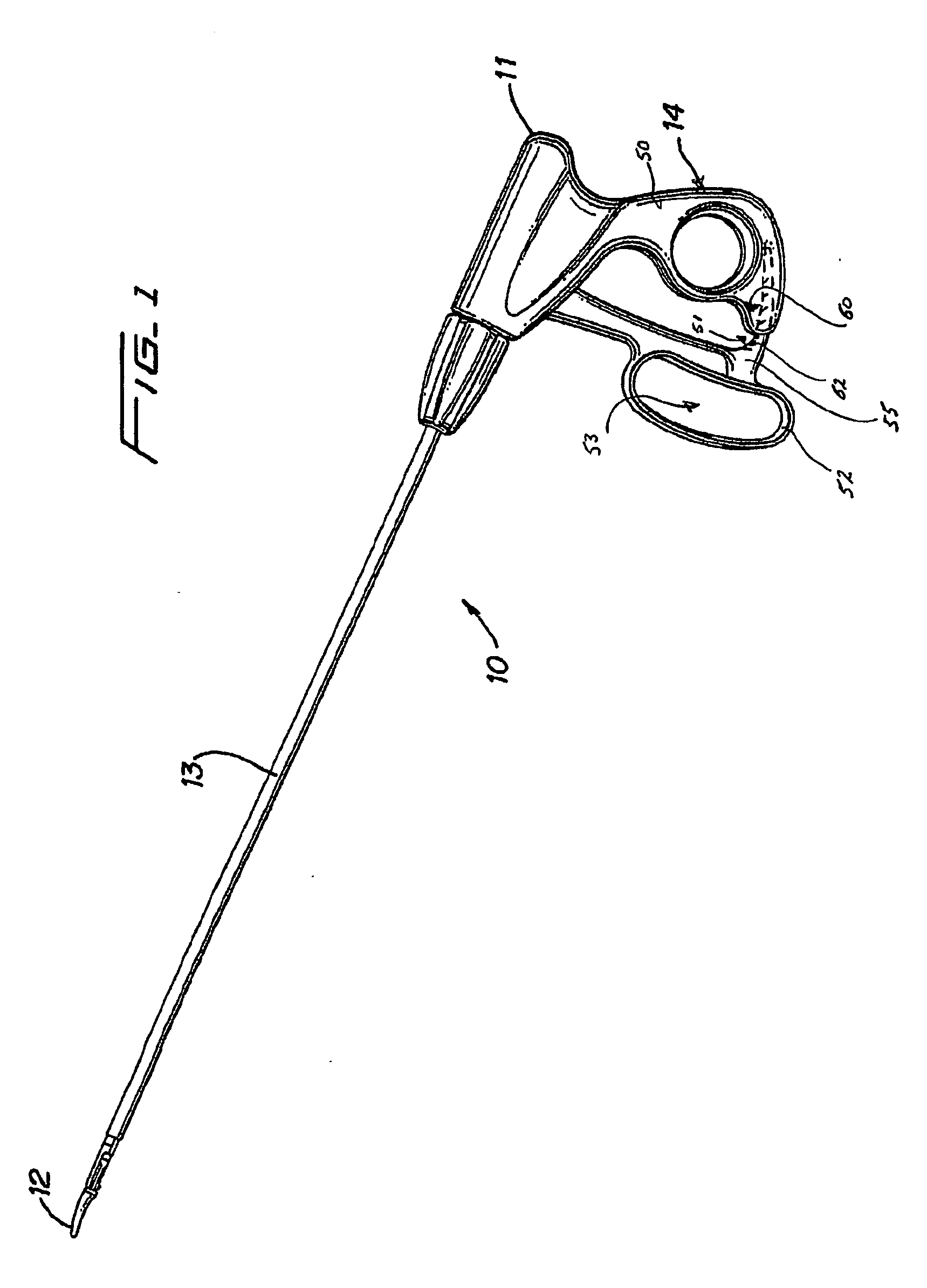
[0012] The present disclosure relates to a laparoscopic bipolar electrosurgical instrument for sealing tissue and includes a handle having an elongated tube affixed thereto. The tube includes first and second jaw members attached to a distal end thereof which are movable from a first position for approximating tissue to at least one subsequent position for grasping tissue therebetween. Each of the jaw members includes an
electrically conductive sealing surface. The handle has a fixed handle and a handle which is movable relative to the fixed handle to effect movement of the jaw members from the first position to the at least one subsequent position for grasping tissue. The jaw members are connected to a source of electrosurgical energy such that the jaw members are capable of conducting bipolar electrosurgical energy through the tissue held therebetween. A stop is included for maintaining a minimum separation distance between opposing sealing surfaces and a
ratchet is included for maintaining a closure force in the range of about 3 kg / cm2 to about 16 kg / cm2 between opposing sealing surfaces. As can be appreciate, the stop member advantageously creates a minimum separation between
electrically conductive opposing sealing surfaces to effect an efficient, consistent and uniform tissue seal.
[0013] Preferably, the stop maintains a minimum separation distance of at least about 0.03 millimeters between opposing sealing surfaces. Advantageously, the stop maintains a minimum separation distance of about 0.03 milimeters to about 0.16 millimeters. The stop may be disposed on at least one of the electrically conductive sealing surfaces, or alternatively, the stop may be located adjacent one of the electrically conductive sealing surfaces. Although it is preferable to locate the stop member on one or both of the electrically conductive opposing sealing surfaces, it may in some instances be advantageous to locate the stop member adjacent the opposing sealing surfaces.
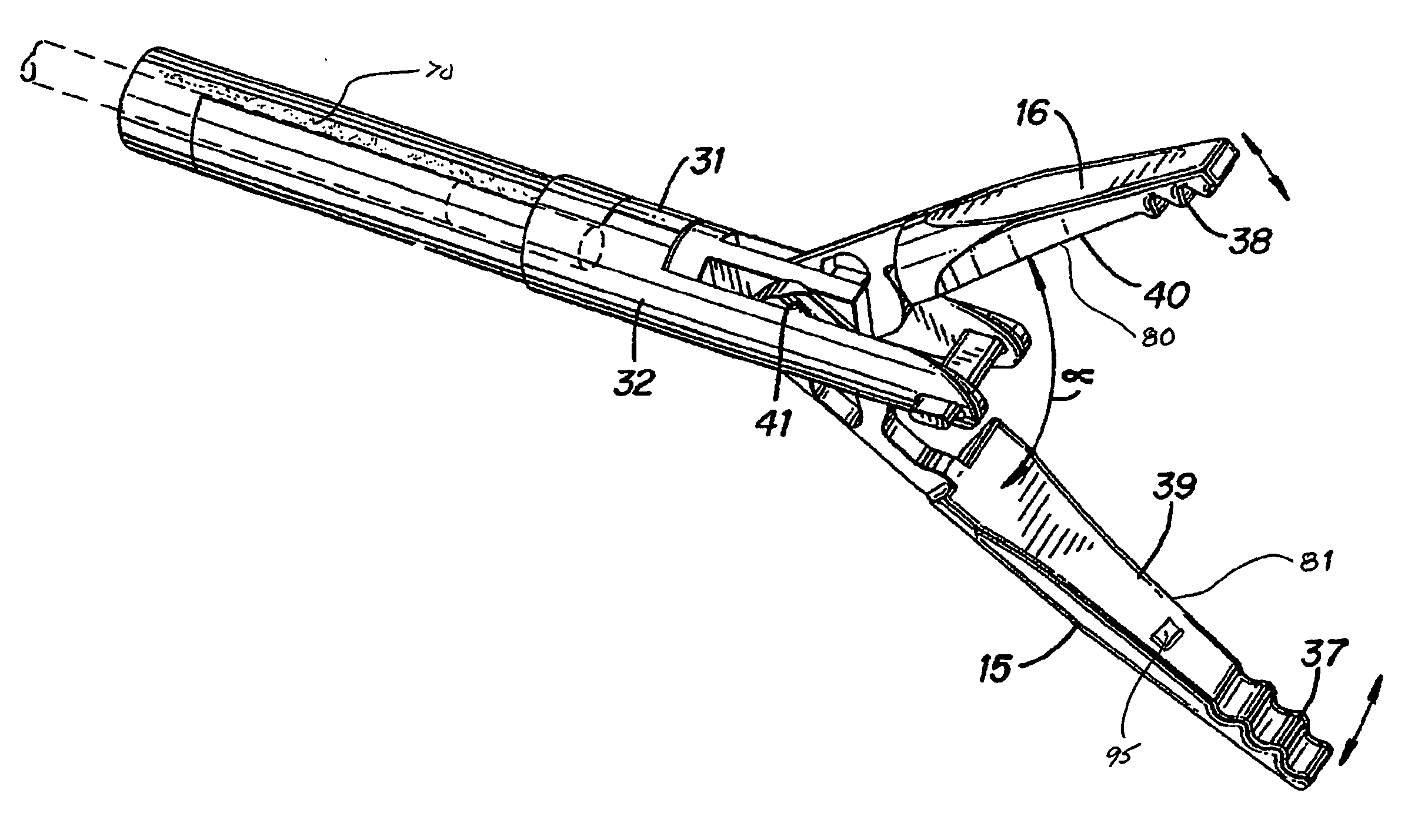
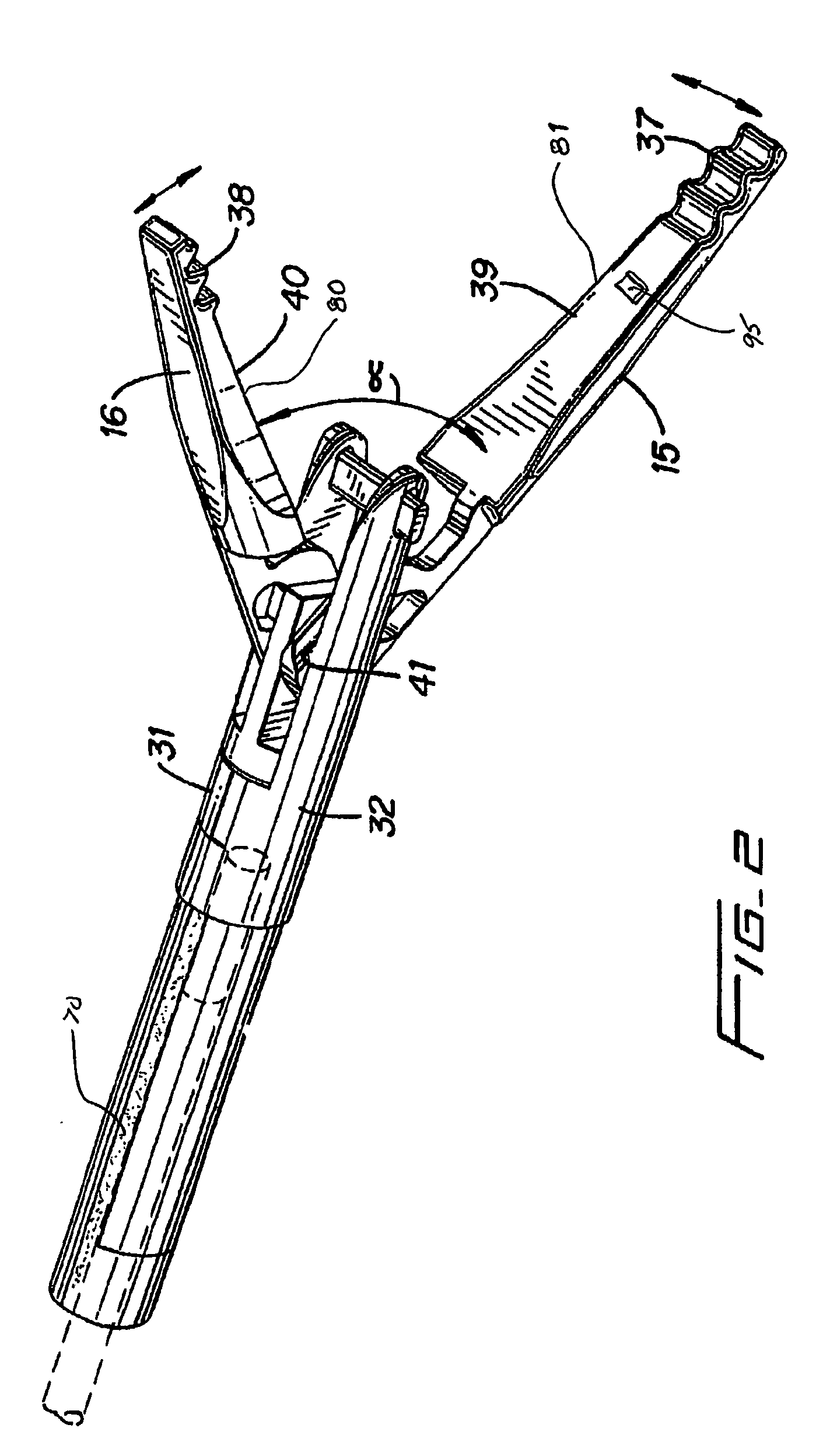
[0014] In one embodiment according to the present disclosure, the first jaw member is connected to the bipolar electrosurgical
energy source by a pushrod and the second jaw member is connected to the bipolar electrosurgical source by a conductive tube. As can be appreciated, isolating the jaw members in this manner reduces the likelihood of the instrument short circuiting during activation.
[0015] In another embodiment, the
ratchet is disposed within the fixed handle and at least one complimentary
interlocking mechanical interface is disposed on the movable handle. Preferably, the ratchet and the complimentary
interlocking mechanical interface provide at least one
interlocking position for maintaining a closure force within the range of about 7 kg / cm2 to about 13 kg / cm2 between opposing sealing surfaces. Ideally, the closure force is in the range of about 4 kg / cm2 to about 6.5 kg / cm2. As can be appreciated and as mentioned herein, maintaining the closure force within the above working ranges is a key factor in producing an effective and consistent seal.
[0018] In one embodiment, the non-stick material is a
coating which is deposited on the opposable sealing surfaces. As can be appreciated, this reduces the likelihood of coagulum build-up and sticking. The non-stick
coating may be selected from a group of materials consisting of: nitrides and
nickel / chrome alloys. Preferably, the non-stick
coating includes one of:
TiN; ZrN; TiAlN; CrN;
nickel / chrome alloys with a Ni / Cr ratio of approximately 5:1;
Inconel 600; Ni200; and Ni201.
[0019] In one embodiment according to the present disclosure, the opposable sealing surfaces are manufactured from a non-stick material which is a
nickel / chrome
alloy. For example, the non-stick material may include nickel / chrome alloys with a Ni / Cr ratio of approximately 5:1,
Inconel 600, Ni200 and Ni201. It is envisioned that these particular materials are advantageous in providing a superior non-stick surface which reduces coagulum build-up and sticking during activation.

