Audio encoding device, audio decoding device, audio encoding method, and audio decoding method

a technology of audio encoding and decoding method, applied in the field of speech encoding apparatus and speech encoding apparatus, can solve problems such as large amounts, and achieve the effect of reducing computation amount and improving the quality of decoding signal

Active Publication Date: 2006-08-03
III HLDG 12 LLC
View PDF10 Cites 43 Cited by
  • Summary
  • Abstract
  • Description
  • Claims
  • Application Information

AI Technical Summary

Benefits of technology

[0008] It is therefore an object of the present invention to provide a speech coding apparatus, speech decoding apparatus and methods thereof enabling scalable coding to be implemented with small amounts of calculation and coded information.
[0009] The above-noted object is achieved by providing an enhancement layer to perform long te...

Problems solved by technology

However, in the conventional scalable coding system, the CELP type speech coding/decoding system is used as the coding schemes...

Method used


Image

  • Audio encoding device, audio decoding device, audio encoding method, and audio decoding method
  • Audio encoding device, audio decoding device, audio encoding method, and audio decoding method
  • Audio encoding device, audio decoding device, audio encoding method, and audio decoding method

Examples


embodiment 1

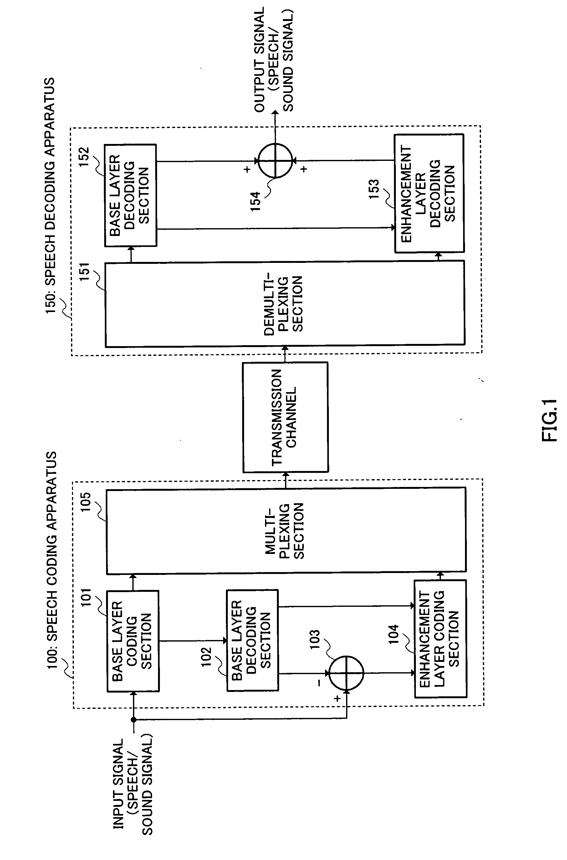
[0021]FIG. 1 is a block diagram illustrating configurations of a speech coding apparatus and speech decoding apparatus according to Embodiment 1 of the invention.

[0022] In FIG. 1, speech coding apparatus 100 is mainly comprised of base layer coding section 101, base layer decoding section 102, adding section 103, enhancement layer coding section 104, and multiplexing section 105. Speech decoding apparatus 150 is mainly comprised of demultiplexing section 151, base layer decoding section 152, enhancement layer decoding section 153, and adding section 154.

[0023] Base layer coding section 101 receives a speech or sound signal, codes the input signal using the CELP type speech coding method, and outputs base layer coded information obtained by the coding, to base layer decoding section 102 and multiplexing section 105.

[0024] Base layer decoding section 102 decodes the base layer coded information using the CELP type speech decoding method, and outputs a base layer decoded signal obta...

embodiment 2

[0087] Embodiment 2 will be described with reference to a case of coding and decoding a difference (long term prediction residual signal) between the residual signal and long term prediction signal.

[0088] Configurations of a speech coding apparatus and speech decoding apparatus of this Embodiment are the same as those in FIG. 1 except for the internal configurations of enhancement layer coding section 104 and enhancement layer decoding section 153.

[0089]FIG. 7 is a block diagram illustrating an internal configuration of enhancement layer coding section 104 according to this Embodiment. In addition, in FIG. 7, structural elements common to FIG. 5 are assigned the same reference numerals as in FIG. 5 to omit descriptions.

[0090] As compared with FIG. 5, enhancement layer coding section 104 in FIG. 7 is further provided with adding section 701, long term prediction residual signal coding section 702, coded information multiplexing section 703, long term prediction residual signal dec...

embodiment 3

[0117]FIG. 9 is a block diagram illustrating configurations of a speech signal transmission apparatus and speech signal reception apparatus respectively having the speech coding apparatus and speech decoding apparatus described in Embodiments 1 and 2.

[0118] In FIG. 9, speech signal 901 is converted into an electric signal through input apparatus 902 and output to A / D conversion apparatus 903. A / D conversion apparatus 903 converts the (analog) signal output from input apparatus 902 into a digital signal and outputs the result to speech coding apparatus 904. Speech coding apparatus 904 is installed with speech coding apparatus 100 as shown in FIG. 1, encodes the digital speech signal output from A / D conversion apparatus 903, and outputs coded information to RF modulation apparatus 905. R / F modulation apparatus 905 converts the speech coded information output from speech coding apparatus 904 into a signal of propagation medium such as a radio signal to transmit the information, and ou...


PUM


Abstract

Base layer coding section 101 encodes an input signal to obtain base layer coded information. Base layer decoding section 102 decodes the base layer coded information to obtain a base layer decoded signal and long term prediction information (pitch lag). Adding section 103 inverts the polarity of the base layer decoded signal to add to the input signal, and obtains a residual signal. Enhancement layer coding section 104 encodes a long term prediction coefficient calculated using the long term prediction information and the residual signal to obtain enhancement layer coded information. Base layer decoding section 152 decodes the base layer coded information to obtain the base layer decoded signal and long term prediction information. Using the long term prediction information, enhancement layer decoding section 153 decodes the enhancement layer coded information to obtain an enhancement layer decoded signal. Adding section 154 adds the base layer decoded signal and enhancement layer decoded signal to obtain a speech/sound signal. It is thereby possible to implement scalable coding with small amounts of calculation and coded information.

Description

TECHNICAL FIELD [0001] The present invention relates to a speech coding apparatus, speech decoding apparatus and methods thereof used in communication systems for coding and transmitting speech and / or sound signals. BACKGROUND ART [0002] In the fields of digital wireless communications, packet communications typified by Internet communications, and speech storage and so forth, techniques for coding / decoding speech signals are indispensable in order to efficiently use the transmission channel capacity of radio signal and storage medium, and many speech coding / decoding schemes have been developed. Among the systems, the CELP speech coding / decoding scheme has been put into practical use as a mainstream technique. [0003] A CELP type speech coding apparatus encodes input speech based on speech models stored beforehand. More specifically, the CELP speech coding apparatus divides a digitalized speech signal into frames of about 20 ms, performs linear prediction analysis of the speech signa...

Claims


Application Information

Patent Timeline
IPC IPC(8): G10L19/12G10L19/24
CPCG10L19/24G10L19/08
Inventor SATO, KAORUMORII, TOSHIYUKI
Owner III HLDG 12 LLC
Why Eureka
Try Eureka