Twin clutch manual gearbox

a manual gearbox and clutch technology, applied in the direction of belt/chain/gearing, toothed gearing, toothed gearing, etc., can solve the problems of reducing unable to retain bearings, and unsatisfactory solutions, so as to reduce the strength of the first input shaft, reduce the bearing span, and high bearing rigidity

Active Publication Date: 2006-08-10
NISSAN MOTOR CO LTD
View PDF10 Cites 12 Cited by
  • Summary
  • Abstract
  • Description
  • Claims
  • Application Information

AI Technical Summary

Benefits of technology

[0021] In such a twin-clutch manual gearbox, upon positioning gearsets associated with a gearbox speed grouping provided between the second input shaft and the layshaft, because the gearset associated with the lowest gearbox speed of the gearbox speeds on the second input shaft (with a gear outer diameter capable of providing a specified bearing retaining space between the first input shaft and the second input shaft) is positioned on the side farthest from the engine, the specified space can be secured for retaining a bearing between the first input shaft and the rearward end of the second input shaft, without forming an annular groove in the first input shaft for retaining a bearing. Thus, a bearing can be retained between the first input shaft and the rearward end of the second input shaft without also reducing the strength of the first input shaft. Therefore, according to the present invention, the bearing span for the bearing provided between both input shafts can be large, which enables maintaining high bearing rigidity between both input shafts.

Problems solved by technology

JP8-320054, is problematic for use as a layshaft in a twin-clutch manual gearbox for an FR vehicle.
Such a gear restricts the size of the annular space between the first input shaft and the rearward end of the second input shaft, so much so that a needle bearing, or other bearing, cannot be retained in the annular space between the first input shaft and the rearward end of the second input shaft.
Forming an annular groove in the first input shaft in which to place said needle bearing would cause decreased strength for the first input shaft, so this solution is not a desirable option.
A possible alternative may be to move the needle bearing toward the engine to a position where no gears are present, but this would cause the needle bearing to approach the bearing between the forward end of the second input shaft and the forward end of the first input shaft, narrowing the bearing span and making the rigidity of the bearing between both input shafts somewhat deficient.
Therefore this alternative solution is also difficult to implement.

Method used


Image

  • Twin clutch manual gearbox
  • Twin clutch manual gearbox
  • Twin clutch manual gearbox

Examples


Embodiment Construction

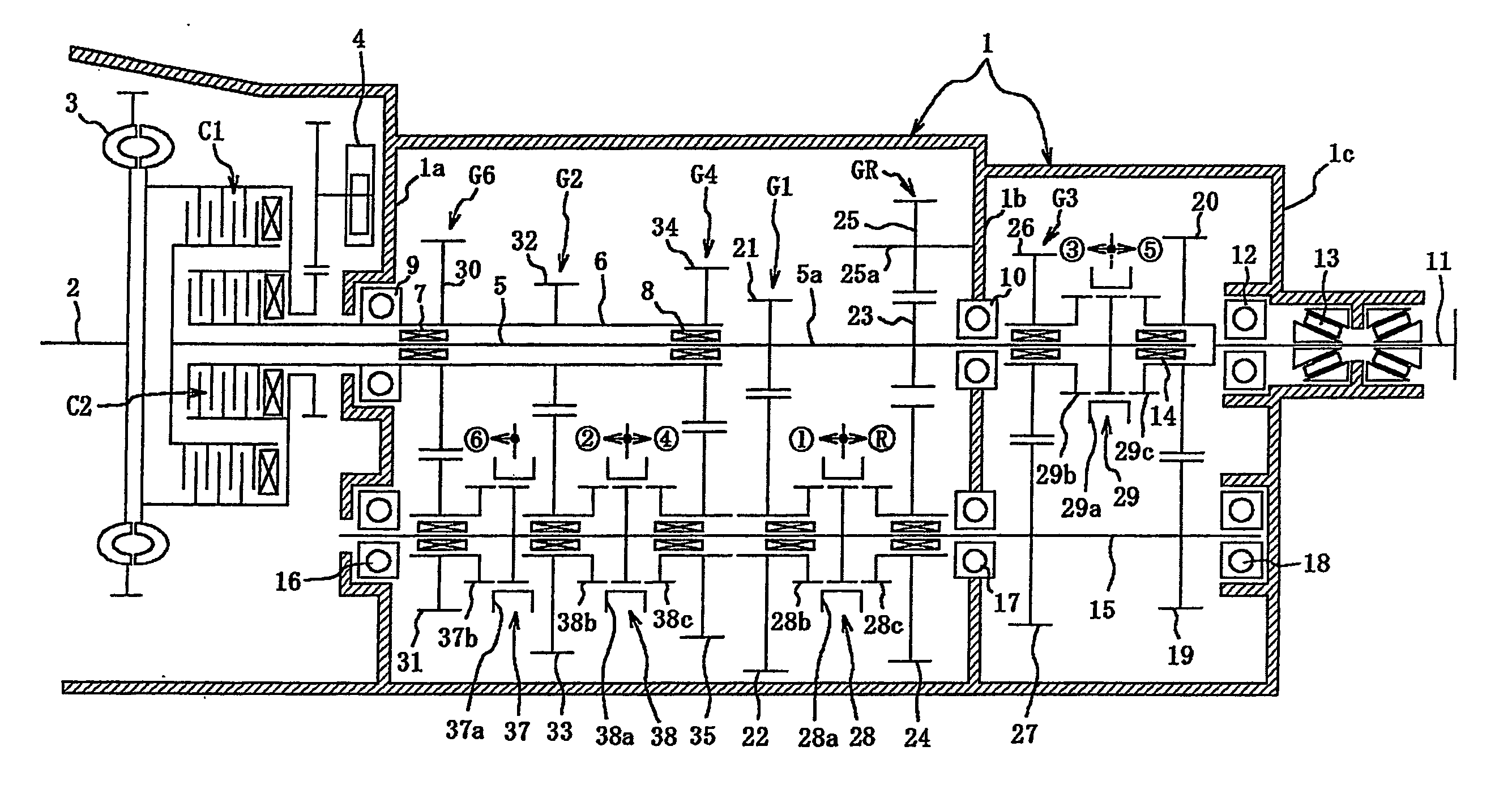
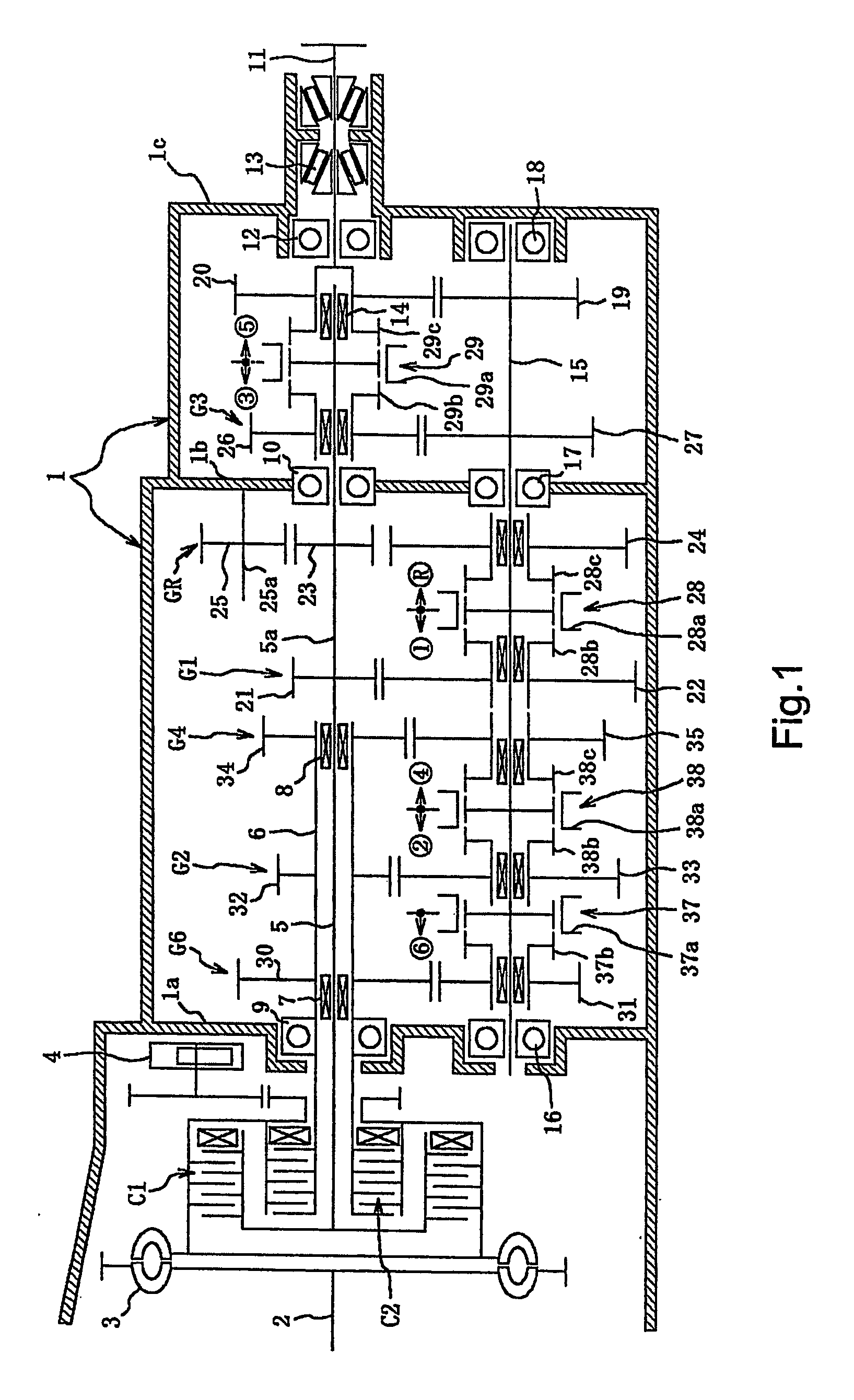
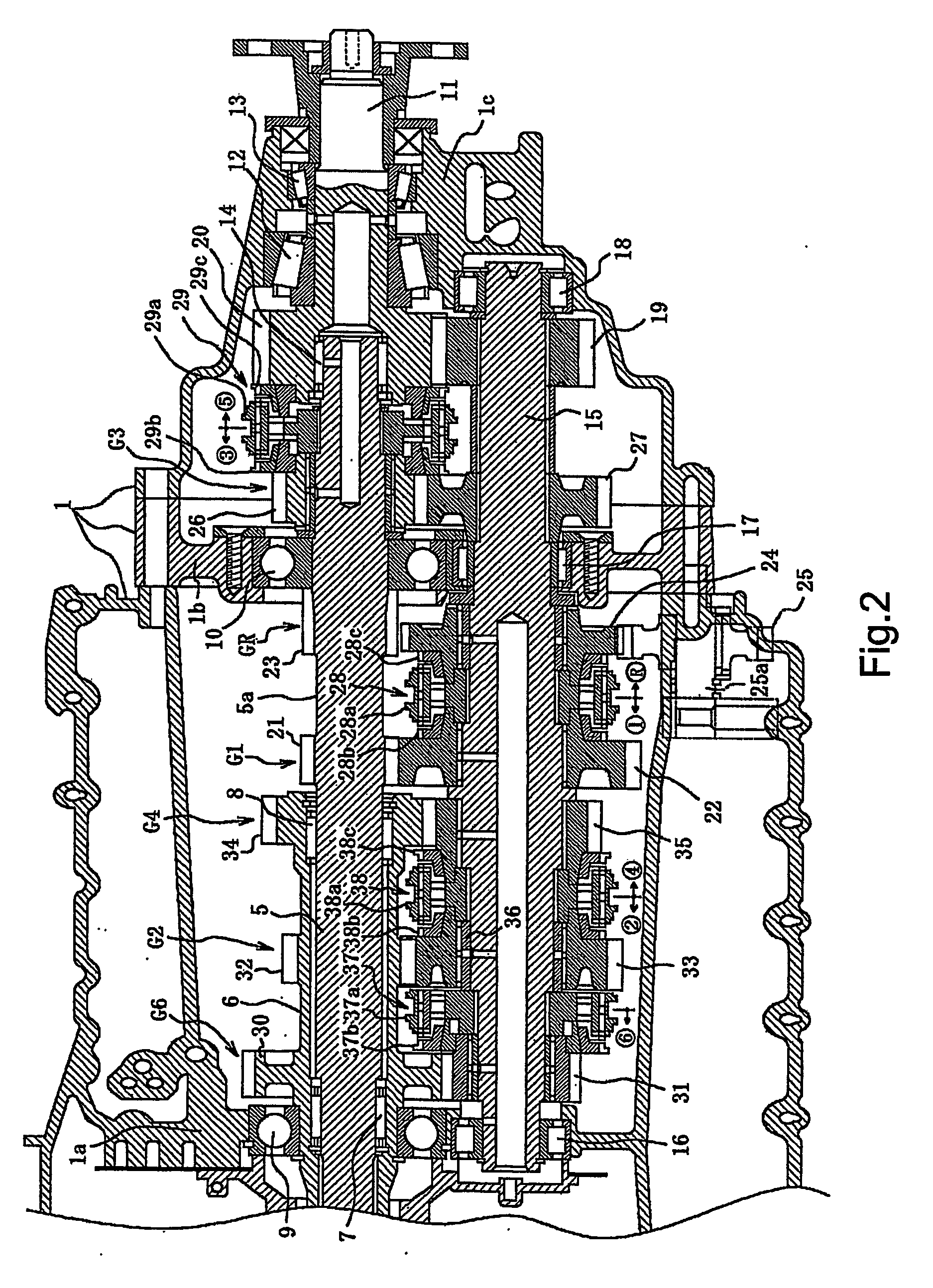
[0033] An embodiment of the present invention is described in detail below, according to the embodiment indicated in the figures. The twin-clutch manual gearbox of this embodiment has the following composition and is useful for a front engine, rear wheel drive vehicle (referred to as an FR vehicle).

[0034] In FIG. 1, a gearbox housing is referred to generally as 1. The gearbox is provided with a first automated clutch, C1, for odd-numbered gearbox speeds (first gear, third gear, fifth gear and reverse gear) and a second automated clutch, C2, for even-numbered gearbox speeds (second gear, fourth gear, sixth gear). The first and second automated clutches, C1 and C2, are interposed between a gearchange mechanism that is housed within the gearbox housing 1, as described further below, and the engine (not identified, although FIG. 1 shows a crankshaft 2 of the engine). Both clutches C1 and C2 are connected to the engine crankshaft 2, buffered via a torsional damper 3. An oil pump 4 is fu...


PUM


Abstract

A twin-clutch manual gearbox has a first input shaft and a second input shaft to which engine rotation is selectively input via individual clutches. The second input shaft is rotatably fitted onto the first input shaft so that the first input shaft protrudes from an end of the second input shaft farthest from the engine. First gearsets are located between the protruding end of the first input shaft and a layshaft located between the first and second input shafts. Second gearsets are located between the second input shaft and the layshaft. The second gearsets are positioned such that the gearset of the lowest gearbox speed which is capable of providing a bearing retaining space between the first input shaft and the second input shaft is positioned farthest from the engine, and the gearset of the highest gearbox speed is positioned closest to the engine.

Description

CROSS-REFERENCE TO RELATED APPLICATIONS [0001] This nonprovisional application claims priority under 35 U.S.C. §119(a) to Japanese Patent Application No. 2004-082299, filed in Japan on Mar. 22, 2004, the entire contents of which are hereby incorporated by reference. BACKGROUND OF THE INVENTION [0002] 1. Field of the Invention [0003] The present invention generally relates to a so-called twin-clutch manual gearbox. More specifically, the present invention relates to a twin-clutch manual gearbox provided with an automated clutch between the engine and the manual gearbox for each gearbox speed grouping. The twin-clutch manual gearbox is useful for performing automated gearchanging by switching between engaging and disengaging these automated clutches (shifting control) and by alternating gearbox speed selection between both gearbox speed groupings. [0004] 2. Background Information [0005] A conventionally known example of such a twin-clutch manual gearbox is the twin-clutch manual gearb...

Claims


Application Information

Patent Timeline
Patent Type & Authority Applications(United States)
IPC IPC(8): F16H3/08F16H3/091F16H3/00
CPCF16H3/006Y10T74/19228Y10T74/19219Y10T74/19288
Inventor TERAI, HIROMU
Owner NISSAN MOTOR CO LTD
Why Eureka
Try Eureka