Software controlled electronic dimming ballast

a software controlled, electronic technology, applied in the direction of electric variable regulation, process and machine control, instruments, etc., can solve the problems of increasing the size of the ballast, occupying a large amount of space in the ballast, and requiring a relatively large number of electronic components

Inactive Publication Date: 2006-08-10
UNIVERSAL LIGHTING TECHNOLOGIES
View PDF6 Cites 76 Cited by
  • Summary
  • Abstract
  • Description
  • Claims
  • Application Information

AI Technical Summary

Benefits of technology

[0016] Another object of the present invention is to provide an electronic dimm...

Problems solved by technology

First, the dimming control circuit in this ballast requires a relatively high number of electronic components, i.e., the dimming control signal conditioning circuit, the microcontroller circuit, the PWM circuit, and the lamp current sensing circuit, and takes up a large amo...

Method used


Image

  • Software controlled electronic dimming ballast
  • Software controlled electronic dimming ballast
  • Software controlled electronic dimming ballast

Examples


Embodiment Construction

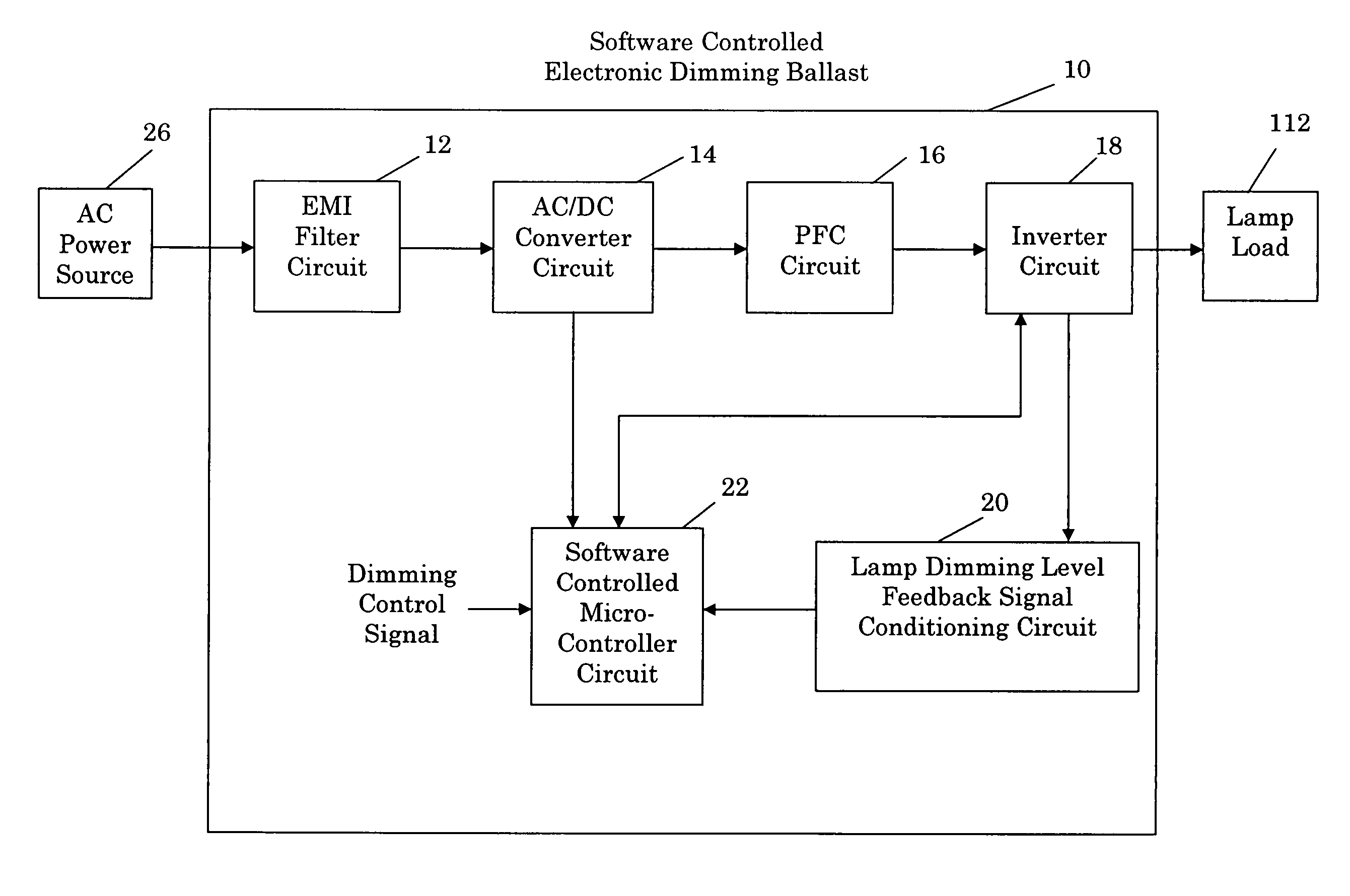
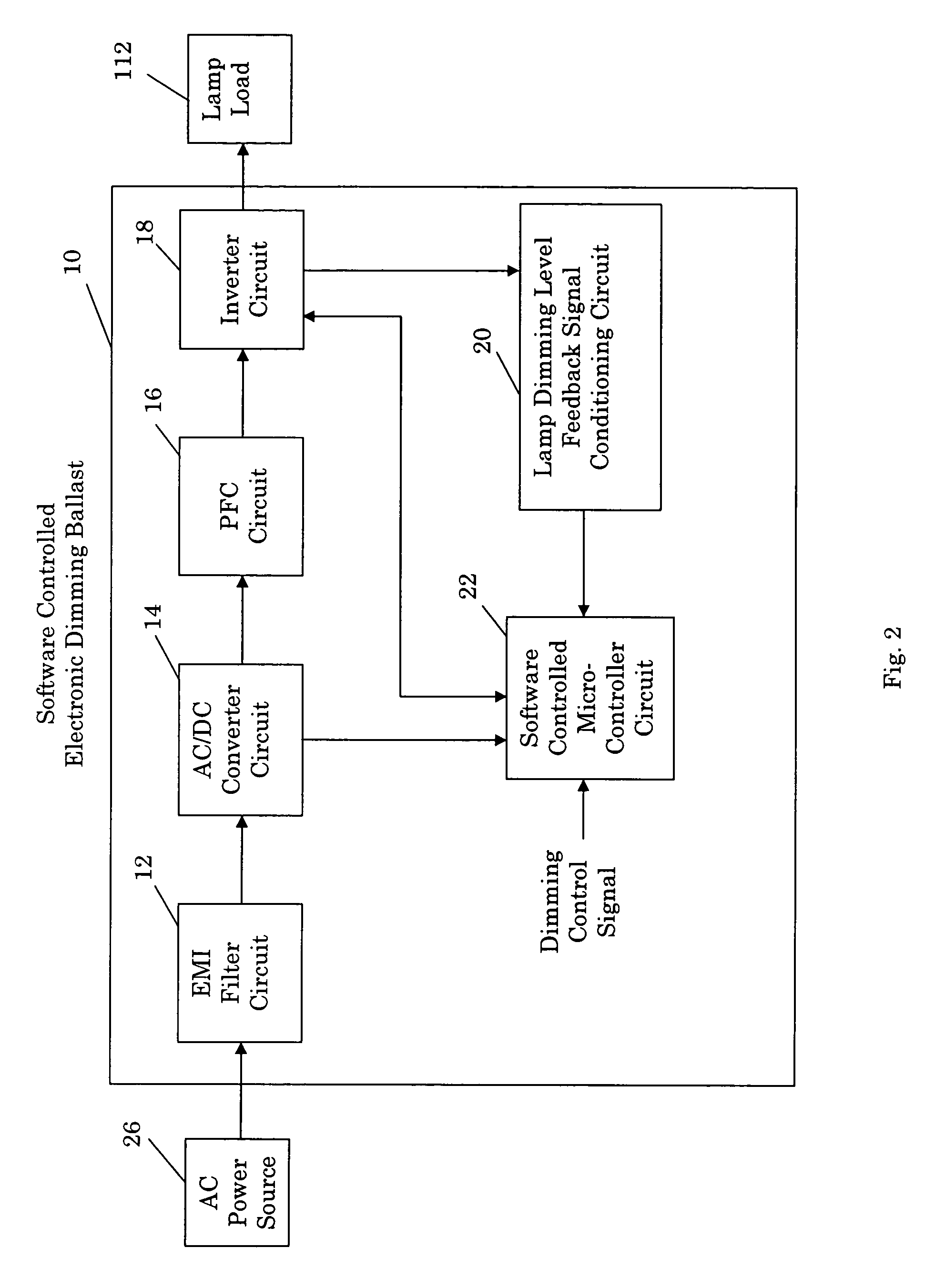
[0032] Referring now to FIG. 2, a preferred embodiment of the software controlled electronic dimming ballast 10 (the “software dimming ballast 10”) of the present invention includes an electromagnetic interference (EMI) filter circuit 12, an alternating current / direct current (AC / DC) converter circuit 14, a power factor correction (PFC) circuit 16, an inverter circuit 18, a lamp dimming level feedback signal conditioning circuit 20, and a software controlled microcontroller circuit 22.

[0033] The EMI Filter Circuit

[0034] The EMI filter circuit 12 includes an EMI input so it can be connected to a 120 volt, 60 Hertz (Hz), sinusoidal AC power source 26 (the “AC power source 26”) and receive low frequency, 60 Hz, sinusoidal AC input voltage (the “AC input voltage”) from that source. The EMI filter circuit 12 generates filtered low frequency sinusoidal AC voltage (the “filtered AC voltage”) by filtering electromagnetic interference, i.e., noise, out of the voltage supplied by the AC pow...


PUM


Abstract

A software controlled electronic dimming ballast for preheating, striking, and varying the dimming level of a lamp. In one embodiment, the ballast includes an EMI filter circuit, an AC/DC converter circuit, a PFC circuit, an inverter circuit, and a software controlled microcontroller circuit. The microcontroller circuit includes a microcontroller and software for generating inverter control signals that cause the inverter circuit to preheat, strike, and varying the dimming level of the lamp. The inverter control signals are generated based on dimming control and lamp dimming level feedback signals. The ballast also includes a lamp dimming level feedback signal conditioning circuit for generating the lamp dimming level feedback signals. Alternative embodiments of the ballast are also described.

Description

APPLICATION FOR UNITED STATES LETTERS PATENT [0001] A portion of the disclosure of this patent document contains material that is subject to copyright protection. The copyright owner has no objection to the facsimile reproduction by anyone of the patent document or the patent disclosure, as it appears in the Patent and Trademark office patent file or records, but otherwise reserves all copyright rights whatsoever. [0002] Be it known that we, Kent E. Crouse, a citizen of the United States, residing in Schaumburg, Ill., William L. Keith, a citizen of the United States, residing in Algonquin, Ill., and Gueorgui L. Grouev, a citizen of Bulgaria, residing in Arlington Heights, Ill., have invented a new and useful “Software Controlled Electronic Dimming Ballast.”BACKGROUND OF THE INVENTION [0003] The present invention relates generally to electronic dimming ballasts for gas discharge lamps. [0004] More particularly, this invention pertains to a software controlled electronic dimming balla...

Claims


Application Information

Patent Timeline
IPC IPC(8): H05B41/36G06F9/00H05B41/282H05B41/38H05B41/392
CPCH05B41/2828H05B41/3925H05B41/3927Y02B20/186Y02B20/00Y10S315/04
Inventor CROUSE, KENTKEITH, WILLIAMGROUEV, GEORGE
Owner UNIVERSAL LIGHTING TECHNOLOGIES
Why Eureka
Try Eureka