Method for detecting a possible collision of at least two objects moving with respect to each other

a technology of at least two objects and collision detection, applied in the direction of programme control, automatic controller, controller with discontinuous output signal, etc., can solve the problems of requiring unnecessary computational time for two objects for collision, using as little computing time, and often observing overlap of utilized envelope bodies

Active Publication Date: 2006-08-10
DR JOHANNES HEIDENHAIN GMBH
View PDF3 Cites 11 Cited by
  • Summary
  • Abstract
  • Description
  • Claims
  • Application Information

AI Technical Summary

Benefits of technology

[0009] Example embodiments of the present invention

Problems solved by technology

In this method, there is believed to be the problem that in order to reliably detect a possible collision of two objects moving with respect to each other, the path line representing the relative positions of the objects to be monitored must be covered using a step size that is as small as possible, since path-line points at which there is the danger of a collision may be skipped when the utilized step size is too large.
This conflicts with the need to carry out the collision monitoring, using as little computing time as possible.
Collision monitoring with the aid of la

Method used


Image

  • Method for detecting a possible collision of at least two objects moving with respect to each other
  • Method for detecting a possible collision of at least two objects moving with respect to each other
  • Method for detecting a possible collision of at least two objects moving with respect to each other

Examples


Embodiment Construction

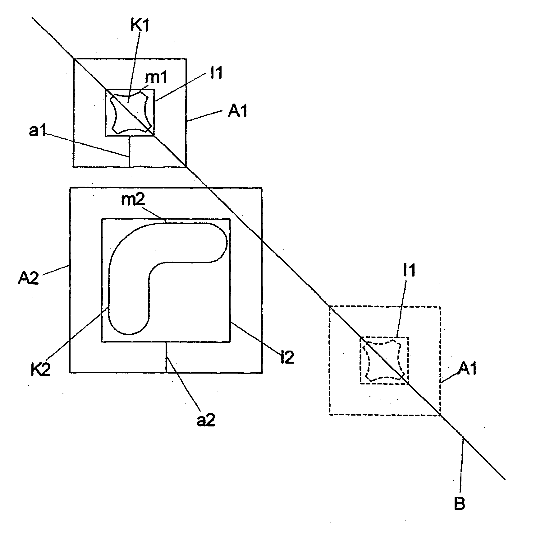
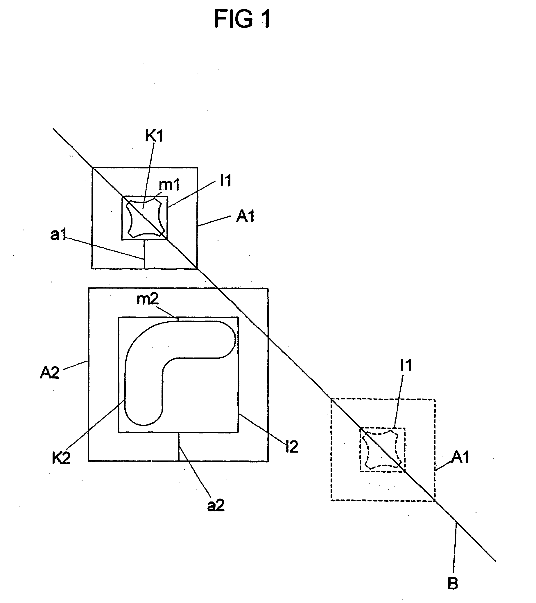
[0044] Illustrated in FIG. 1 are two objects moving with respect to each other in the form of two bodies K1, K2, which may be machine parts of a machine tool, and which, within the scope of the working steps to be executed by the machine, may be moved with respect to each other along a path line B specified by the machine control unit.

[0045] In order to determine if the intended relative movement of the two bodies K1, K2 along a path line B, specifiable by the machine control unit, may result in a collision of the two bodies K1, K2, their relative motion is simulated by the machine control unit or a processor coupled to the machine control unit, prior to the actual execution of the corresponding machine operations. Therefore, it is checked in advance if contact of the two bodies K1, K2 would occur in the case of a movement of the two bodies K1, K2 along path line B. In such a situation, the corresponding machine operation may not be carried out.

[0046] To carry out this collision m...


PUM


Abstract

A method is for detecting a possible collision of at least two objects moving with respect to each other by simulating the intended relative motion of the two objects. At least one of the objects is assigned an envelope surrounding the object, the path line represents the relative motion of the objects is covered in steps of a defined step size, and the occurrence of an overlap of the objects is detected for ascertaining a possible collision of the objects. For at least one object, the outer contour of the corresponding envelope is used as a datum for detecting an overlap. At least one object is assigned an inner and an outer envelope, of which the inner envelope surrounds the object and the outer envelope surrounds the inner envelope. The outer envelope is used as a datum for detecting an overlap of the two objects, and when an overlap is detected in a segment of the path line, the segment of the path line is re-traversed using a smaller, second step size. When the segment of the path line is re-traversed, the inner envelope of at least one of the objects is used as a datum for detecting an overlap.

Description

CROSS-REFERENCE TO RELATED APPLICATIONS [0001] The present application claims priority to Application No. 10 2004 062 163.2, filed in the Federal Republic of Germany on Dec. 20, 2004, which is expressly incorporated herein in its entirety by reference thereto. FIELD OF THE INVENTION [0002] The present invention relates to a method for detecting a possible collision of at least two objects moving with respect to each other. BACKGROUND INFORMATION [0003] In such a method, the intended relative movement of the at least two objects moving with respect to each other is simulated, where at least one of the objects is assigned an envelope surrounding the object. The path line representing the relative movement of the two objects is then covered in steps of a defined step size. To detect a possible collision of the objects, the occurrence of an overlap of the two (simulated) objects is detected while the path line is covered. For at least one of the objects, the outer contour of the corresp...

Claims


Application Information

Patent Timeline
IPC IPC(8): G05B19/25
CPCG05B19/4061G05B2219/49145
Inventor HAUNERDINGER, JOSEF
Owner DR JOHANNES HEIDENHAIN GMBH
Why Eureka
Try Eureka