Current-mode control for switched step up-step down regulators

a regulator and step down technology, applied in the direction of dc-dc conversion, power conversion systems, instruments, etc., can solve the problems of difficulty in compensating for boost and buck-boom mode closed loop operation, and achieve the effect of short transition times and saving power

Active Publication Date: 2006-08-10
ANALOG DEVICES INT UNLTD
View PDF33 Cites 52 Cited by
  • Summary
  • Abstract
  • Description
  • Claims
  • Application Information

AI Technical Summary

Benefits of technology

[0015] When the input voltage is slightly less than or the same as the preset output voltage, the first and third switch are turned on at the beginning of each cycle, followed by a brief turn on of the second and fourth switch. The first and third switches are turned on upon receipt of each clock pulse. An advantage of the disclosed arrangements is that switch over between buck and boost modes can be made automatically with very short transition times.
[0016] In another aspect of the disclosure, current mode regulation is carried out with the use of a single current sensing element. The element may be connected in series with the inductor between the first and fourth switches in the four switch implementation or between the first switch and the second switch in the two switch implementation. Alternatively, the single current sensing element may connected directly between the common node and a junction of the second and third switches in the four switch implementation or a junction of the first rectifying device and the second switch in the two switch implementation. In these latter implementations, the current sensing element conducts current only during a portion of the control cycle, thereby conserving power.

Problems solved by technology

The voltage mode control technique used presents difficulty in compensating for boost and buck-boost mode closed loop operation.

Method used


Image

  • Current-mode control for switched step up-step down regulators
  • Current-mode control for switched step up-step down regulators
  • Current-mode control for switched step up-step down regulators

Examples


Embodiment Construction

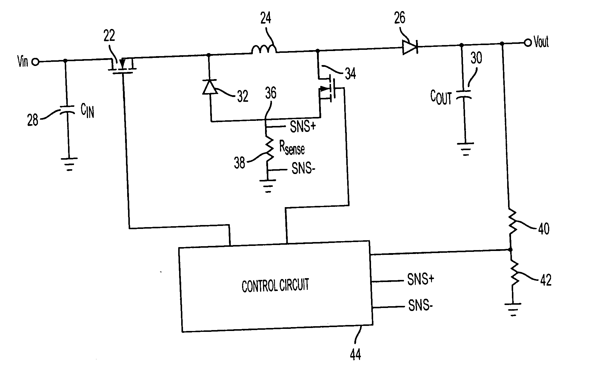
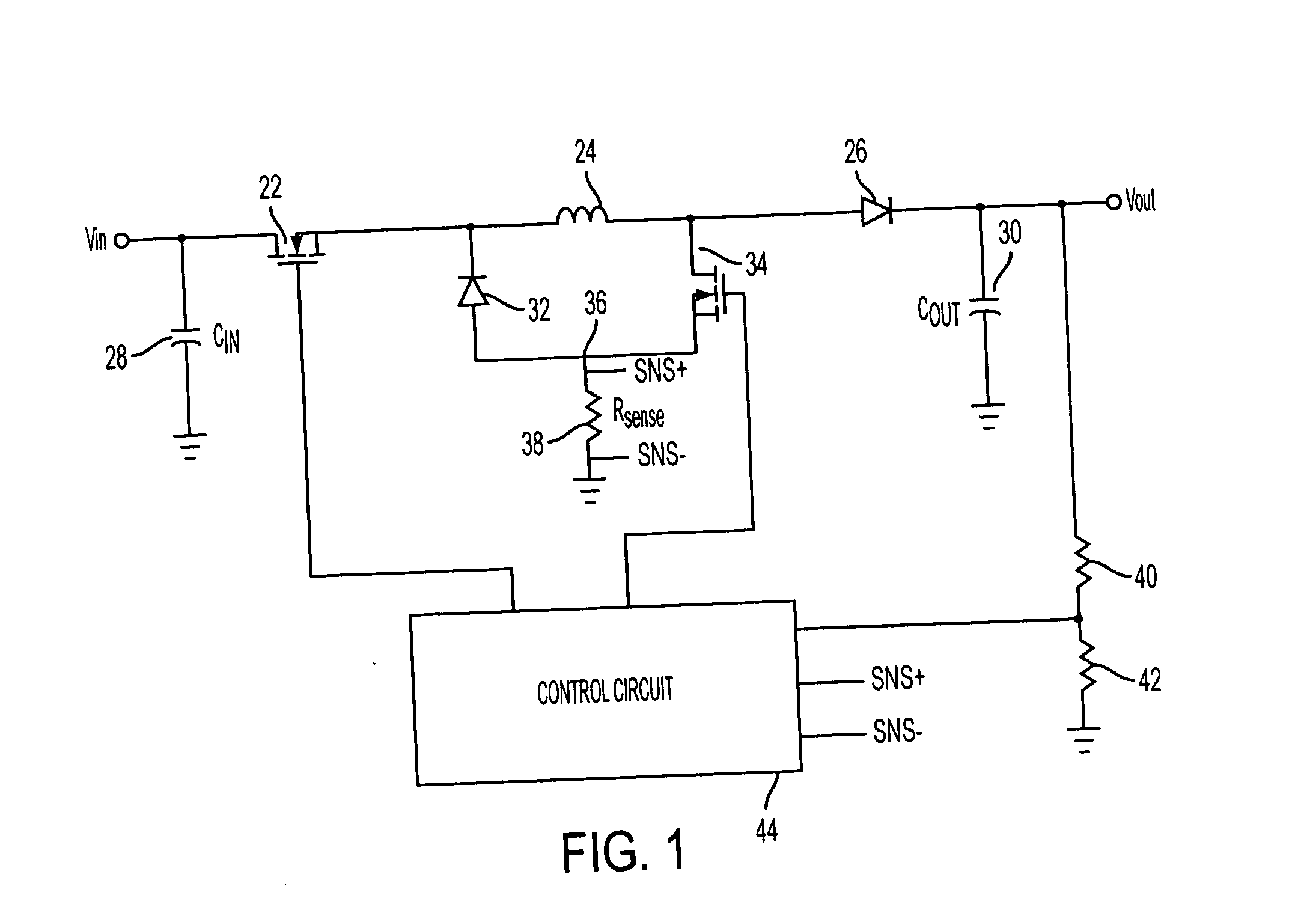
[0030] A switching regulator is represented in the schematic block diagram of FIG. 1. An input voltage from a power supply is applied to input terminal Vin. A preset output voltage is regulated at the Vout terminal. Connected in series between the input and output terminals are a first switch 22, inductor 24, and rectifier 26. Rectifier 26 is connected to conduct current in the direction of the output terminal. Switch 22 preferably is a MOSFET, although any controlled switching device may be utilized.

[0031] An input capacitor 28 is connected between the input terminal and the common ground. An output capacitor 30 is connected between the output terminal and the common ground. Rectifier 32 and a second switch 34 are connected across inductor 24 and joined at node 36. Rectifier 32 is connected to conduct current in the direction of the inductor 24. Current sense resistor 38 is connected between node 36 and the common ground. Voltage divider resistors 40 and 42 are connected in series...


PUM


Abstract

A switched regulator circuit provides step-up and step-down operation in which the level of the input voltage can be greater, equal to, or less than a preset controlled output voltage. A four switch arrangement or two switch arrangement provides buck, boost, and buck-boost regulation under constant frequency valley-peak current mode control. A single sense resistor may be utilized for sensing inductor current during only a short period during each duty cycle. As an alternative to the sense resistor, the switches themselves can be used to sense current during operation.

Description

RELATED APPLICATIONS [0001] This application contains subject matter related to copending U.S. Application number (Attorney docket no. 70386-028) of Flatness et al., filed _, copending U.S. Application number (Attorney docket no. 70386-046) of Flatness et al., filed _, and copending U.S. Application number (Attorney docket no. 70386-047) of Flatness et al., filed _, all commonly assigned with the present application. The disclosures of these applications are incorporated by reference herein.TECHNICAL FIELD [0002] The present disclosure relates to control of regulators, more particularly to switched regulators that can be operated in a boost mode, a buck mode and a buck-boost mode. BACKGROUND [0003] Voltage regulators are known that can convert from input voltages above, below, or equal to the controlled output voltage, respectively performing buck mode regulation, boost mode regulation, or buck-boost mode regulation. Regulator architecture typically is provided for power supplies fo...

Claims


Application Information

Patent Timeline
Patent Type & Authority Applications(United States)
IPC IPC(8): G05F1/40G05F1/618
CPCH02M3/156H02M3/1582
Inventor FLATNESS, RANDY G.ZHOU, XUNWEI
Owner ANALOG DEVICES INT UNLTD
Why Eureka
Try Eureka