RF-resonator tuning

a technology of resonance resonance and tuning components, which is applied in the direction of resonances, waveguide devices, basic electric elements, etc., can solve the problems of increasing the number of problems of standard tuning components, increasing the labor cost of mounting screws/nuts, and high cost of components that are commonly available on the market, so as to achieve the effect of repeatability, cost-effectiveness and straightforward

Inactive Publication Date: 2006-08-10
ALCATEL LUCENT SAS
View PDF5 Cites 4 Cited by
  • Summary
  • Abstract
  • Description
  • Claims
  • Application Information

AI Technical Summary

Benefits of technology

[0008] The inventive RF-resonator separates the functionalities of ‘forced mechanical movement’ and ‘electromagnetic field manipulation’ which are traditionally combined in one component. In such a way any, even minor, gaps in the resonator are avoided as would exist between threaded parts. By applying a mechanical force on the conductive sheet material, an elastic or inelastic deformation of the sheet material is generated which changes the electromagnetic field inside the cavity in order to compensate for manufacturing tolerances of the cavity.
[0016] In a preferred embodiment the resonator body is made of a die cast part. Using a die cast part instead of a milled block for forming the resonator body, manufacturing costs are reduced. Preferably, the cover is also made of a die cast part.

Problems solved by technology

These components are commonly available on the market, but expensive.
Their price is caused by gold-plating, choice of specialized materials, labor cost for mounting the screw / nut / rod subassembly as well as very expensive means to assure good and constant long-term (30 years) contact from screw to nut all around the screw's circumference, e.g. by introduction of individual spring-loaded slits in the screw.
Going to higher and higher frequencies, standard tuning components introduce more and more problems due to their increasing relative size to wavelength ratio.
On the other hand, screw manufacturing costs increase dramatically when trying to keep screw diameter small compared to free-space wavelength (e.g. 3.5 mm for 85 GHz) with manufacturing tolerances scaled down as well.
The state-of-the-art components become more and more fragile to handle as well.

Method used


Image

  • RF-resonator tuning
  • RF-resonator tuning

Examples


Embodiment Construction

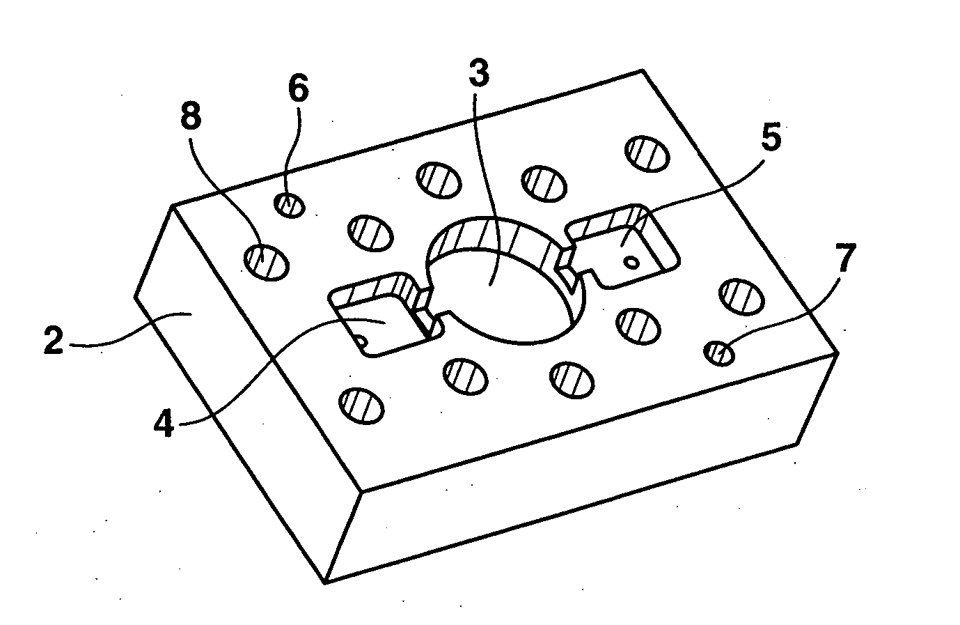
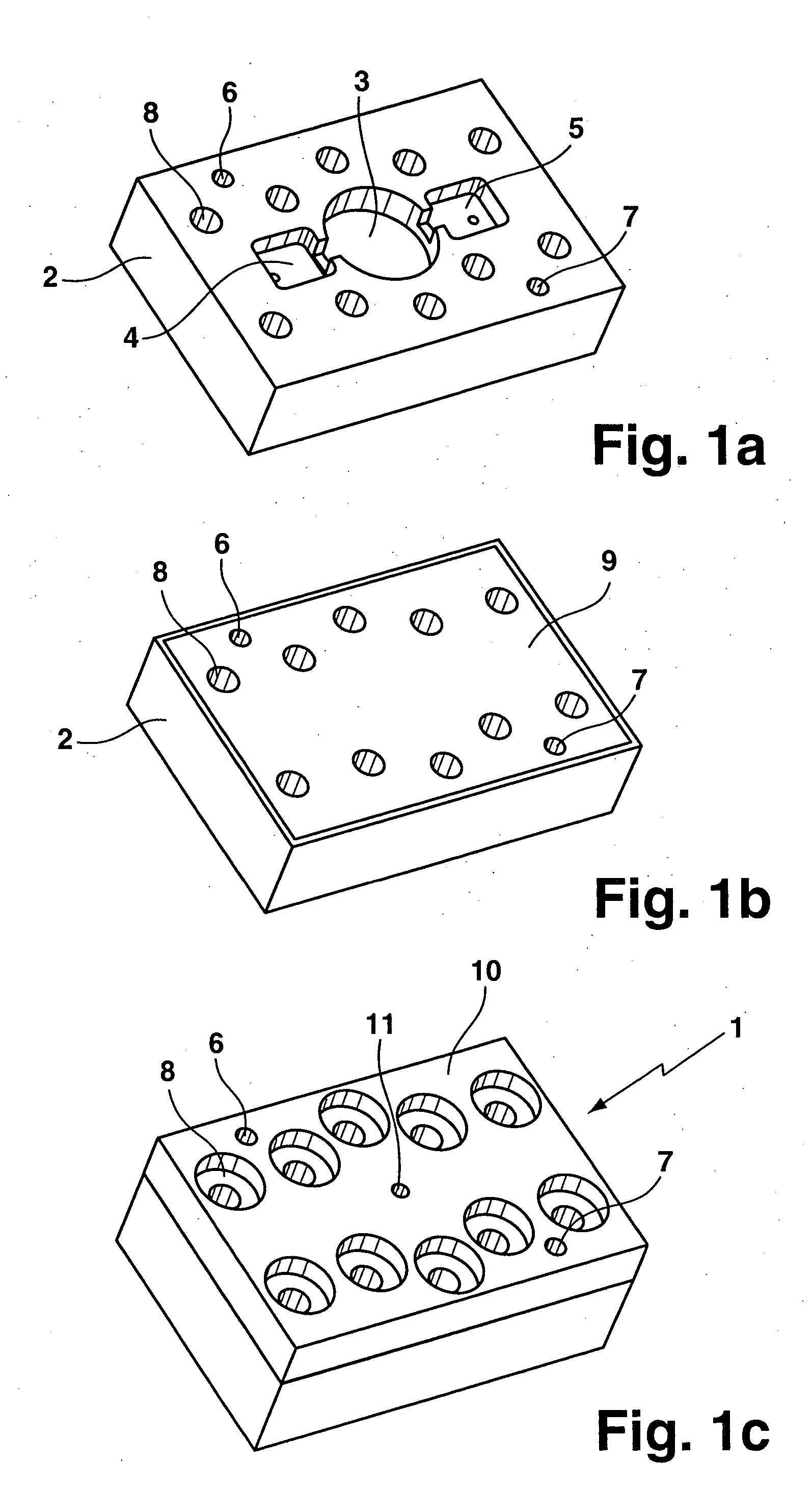
[0023] In FIG. 1a to FIG. 1c three steps of assembling a prototype RF-resonator 1 are shown. With reference to FIG. 1a, a rectangular milled block forms a resonator body 2 which contains a centered cylindrical hole as a resonant cavity 3. To the left and to the right of the cavity 3, two rectangular holes 4, 5 are formed in the resonator body 2 for receiving a first and a second connector (not shown) being inserted through two pinholes from the bottom of the resonator body 2. Two centering pinholes 6, 7 and ten threaded holes 8 are formed on the resonator body 2 as well.

[0024] With reference now to FIG. 1b, the top face of the resonator body 2 of FIG. 1a is covered with a thin metal foil 9 which has holes at the positions of the pinholes 6, 7 and the threaded holes 8. The metal foil 9 covers the resonant cavity 3 and is fixed by mounting a thick cover 10 on top of the resonator body 2, as shown in FIG. 1c. The two pinholes 6, 7 and ten threaded holes 8 formed in the resonator body ...


PUM


Abstract

A RF-resonator (1) comprises a resonator body (2) with at least one resonant cavity (3). A conductive sheet material forms a surface area of the resonant cavity (3), the conductive sheet material being deformable by application of a mechanical force for tuning the resonator to a target frequency. A method for tuning the RF-resonator, comprising the following steps: measuring the resonance frequency of the resonant cavity (3), and deforming the conductive sheet material by applying an increasing mechanical force to the conductive sheet material until the target frequency of the resonant cavity (3) is reached.

Description

[0001] The invention is based on a priority application EP 05 290 294.7 which is hereby incorporated by reference. FIELD OF THE INVENTION [0002] The invention relates to a RF-resonator comprising a resonator body with at least one resonant cavity and a method for tuning the same. BACKGROUND OF THE INVENTION [0003] Electronic systems which use extremely high radio frequencies (RF), such as optical data transmission equipment or millimeter wave radio, either point-to-point or point to multipoint, as well as telematic equipment and subscriber access systems require resonators and filters with a precisely adjusted resonator frequency. [0004] To assure tunability of manufactured raw filter components to a desired exact target frequency, the state of the art makes use of special microwave tuning components (e.g. metallic screws / dielectric rods). These components are commonly available on the market, but expensive. Their price is caused by gold-plating, choice of specialized materials, lab...

Claims


Application Information

Patent Timeline
Patent Type & Authority Applications(United States)
IPC IPC(8): H01P7/06
CPCH01P7/06H01P11/008
Inventor JUNGINGER, BERNHARD
Owner ALCATEL LUCENT SAS
Why Eureka
Try Eureka