Two Dimensional Layout, High Noise Immunity, Interleaved Channels Electrostatic Encoder

an electrostatic encoder and interleaved channel technology, applied in the field of electrostatic capacity type encoders, can solve the problems of complex manufacturing, electrical noise sensitiveness, capacitive sensors, etc., and achieve the effects of simple and cheaper production, less sensitive to vibration and shock, and small siz

Inactive Publication Date: 2006-08-10
BAR ON DAVID
View PDF24 Cites 24 Cited by
  • Summary
  • Abstract
  • Description
  • Claims
  • Application Information

AI Technical Summary

Benefits of technology

[0009] Accordingly, it is an object of the present invention to provide an electrostatic capacity type encoder which enables the device...

Problems solved by technology

Capacitive Sensors, as described in previous patents, ar...

Method used


Image

  • Two Dimensional Layout, High Noise Immunity, Interleaved Channels Electrostatic Encoder
  • Two Dimensional Layout, High Noise Immunity, Interleaved Channels Electrostatic Encoder
  • Two Dimensional Layout, High Noise Immunity, Interleaved Channels Electrostatic Encoder

Examples


Embodiment Construction

[0028] In the following description, for purposes of explanation, specific numbers, materials and configurations are set forth in order to provide a thorough understanding of the present invention. However, it will be apparent to one skilled in the art that the present invention may be practiced without the specific details. In other instances, well known features are omitted or simplified in order not to obscure the present invention.

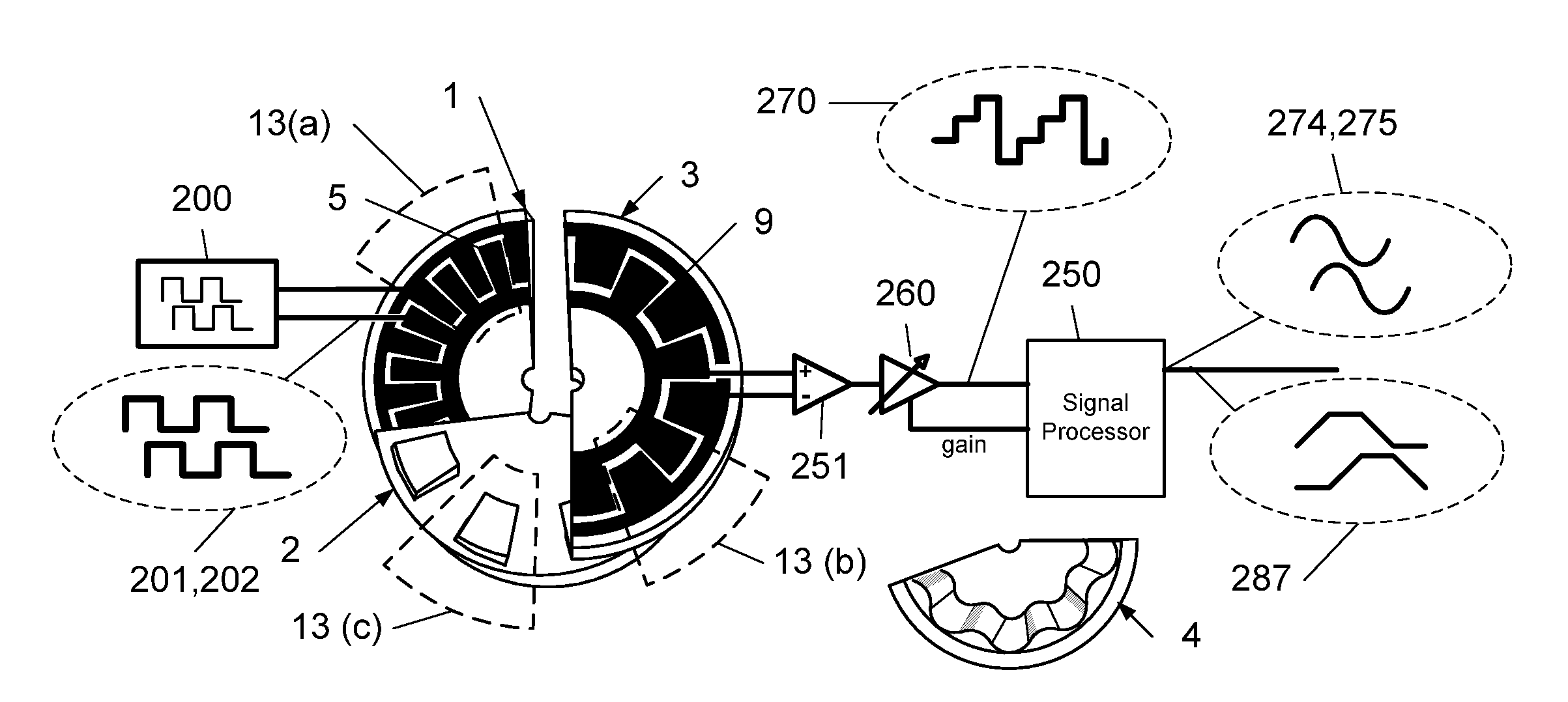
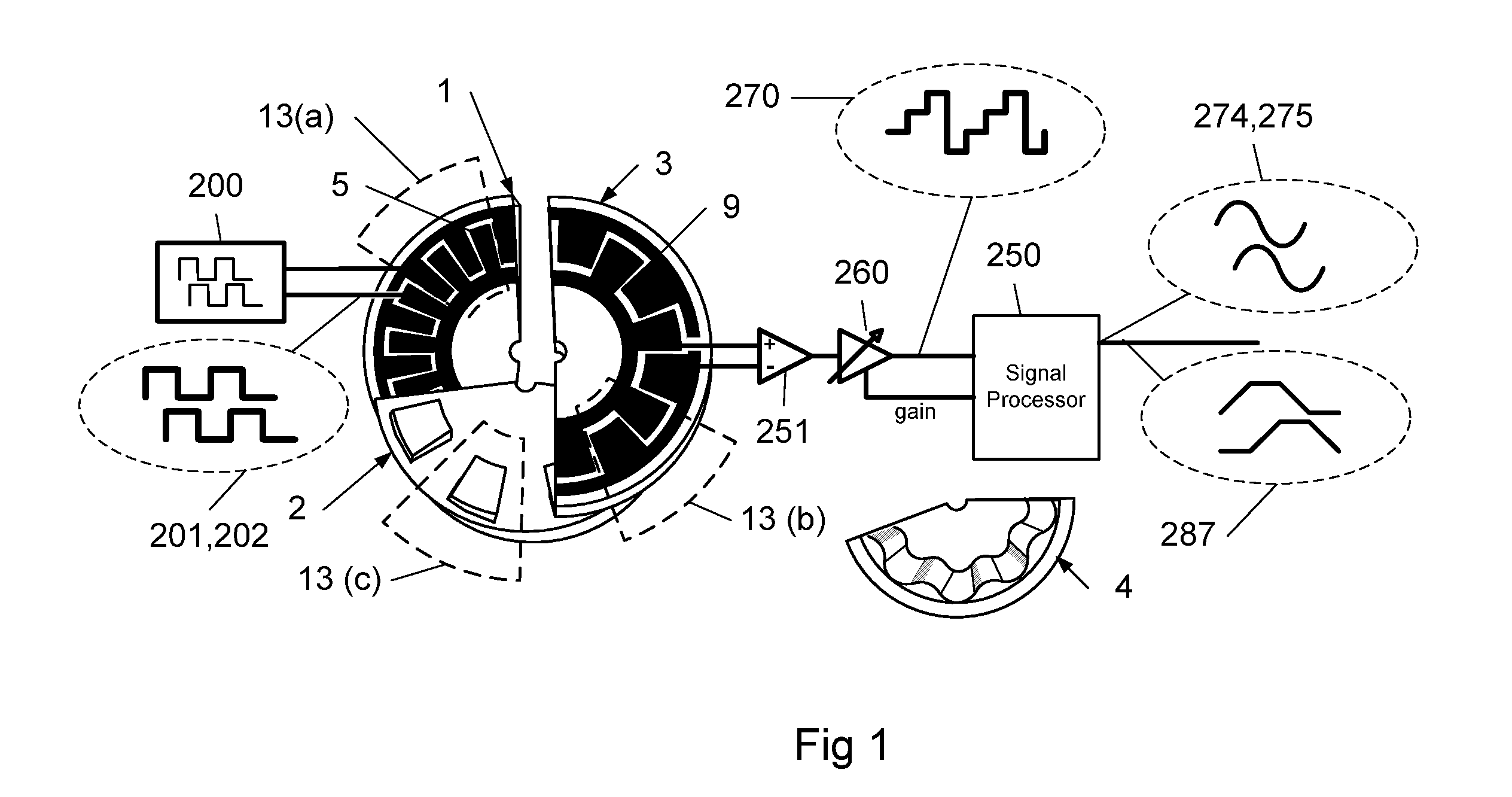
[0029]FIG. 1 illustrates the main components of the present invention single channel rotary encoder; where an excitation generator 200 generate two perpendicular square signals 201, 202 to two sets of metal transmit plates 5 printed on a single plane of a Printed Circuit Board [PCB]. Those static transmitter 1 plates, together with a rotating rotor 2 made of dielectric material, and two sets of static receiving plates 9 imprinted on the receiver 3, form the four different variable capacitors, needed to electrically detect the relative position of the ...


PUM


Abstract

The present invention relates to an electrostatic capacity type encoder which includes a variable capacitance mechanism made on two dimensional planes, random time varying excitation generation system, interlaced fine & coarse cycles and digital signal processing unit. A variable capacitance mechanism which includes stationary and rotating disks facing each other and forming one or more variable capacitors. The transmit electrodes are split to two transmit phases and the receive electrodes to two receive phases, both can be implemented on two dimensional printed circuit boards without third dimension via interconnects. The combination of the 2 by 2 grid provides the four combinations required to detect both position and direction. Another configuration is made of electrostatic capacity type encoder which includes a first and second stationary disks and in between a third rotating disk, made either of a dielectric material with varying geometry or thickness or from a conductive patterns printed on a PCB. A time varying excitation system with no fundamental frequency is described to improve the robustness to external noise and omit the necessacity of excessive shielding. Interlacing mechanism is explained to put several different encoders channels on the same perimeter, minimizing encoder mechanical dimensions. To complete the sensor a digital signal processing unit is presented, where the capacitance value is converted to conventional encoder formats.

Description

FIELD OF THE INVENTION [0001] The present invention relates to an electrostatic capacity type encoder, and more particularly to an improvement of the electrostatic capacity type encoder which electrically detects relative rotary displacement between rotary disks, or linear displacement between two components. PRIOR ART [0002] In the prior art exists several measuring apparatus using an encoder which converts the displacement of a rotor moving along three distinctive transmitter plates referred as R, S, T or four distinctive transmitter plates referred as F1, F2, F3, F4. The implementation of three or more distinctive plates required three dimensional PCB design with one via interconnection per plate as in U.S. Pat. No. 2,534,505 and U.S. Pat. No. 4,788,546. As capacitive signal is highly prune to external interference, external shielding was suggested in U.S. Pat. No. 5,099,386. In U.S. Pat. No. 6,492,911 a labyrinth was added to further block interference from entering the sensor t...

Claims


Application Information

Patent Timeline
IPC IPC(8): G08C19/10
CPCG01D5/2405G01D5/2415
Inventor BAR-ON, DAVID
Owner BAR ON DAVID
Why Eureka
Try Eureka