Method and system to correct motion blur and reduce signal transients in time-of-flight sensor systems

a sensor system and motion blur technology, applied in distance measurement, surveying and navigation, instruments, etc., can solve problems such as yielding a depth image with errors

Active Publication Date: 2006-08-10
MICROSOFT TECH LICENSING LLC
View PDF2 Cites 34 Cited by
  • Summary
  • Abstract
  • Description
  • Claims
  • Application Information

AI Technical Summary

Benefits of technology

[0019] Additional benefits arise from providing clocks of different phases simultaneously to different detectors in pixels, or groups of pixels. The advantage of the invention is to reduce the charge being transferred or current being drawn by circuits connected to the clock signals at any given time, thus reducing undesired voltage or current fluctuations on power, ground, reference, bias or signal nodes in the TOF system. This in turn reduces signal integrity problems in the resulting TOF system.

Problems solved by technology

However such systems may erroneously yield the same measurement information for a distant target object that happens to have a shiny surface and is thus highly reflective, as for a target object that is closer to the system but has a dull surface that is less reflective.
The undesired result is that the motion blur will cause erroneous distance Z data, and will yield a depth image with errors.
These undesired fluctuations translate into depth measurement errors or ‘noise’ in the result and are referred to as signal integrity problems.

Method used


Image

  • Method and system to correct motion blur and reduce signal transients in time-of-flight sensor systems
  • Method and system to correct motion blur and reduce signal transients in time-of-flight sensor systems
  • Method and system to correct motion blur and reduce signal transients in time-of-flight sensor systems

Examples


Embodiment Construction

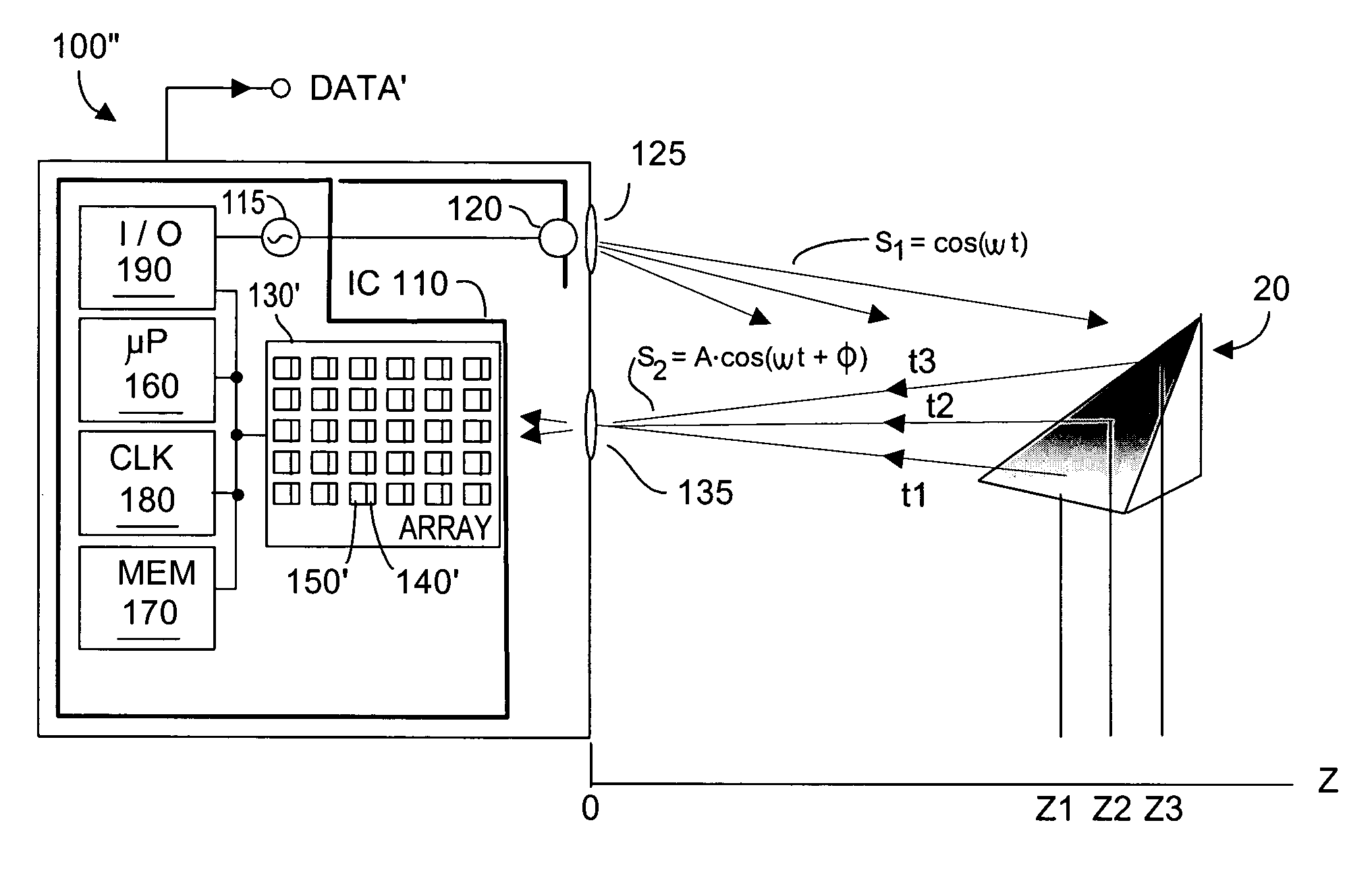
[0033]FIG. 3A depicts a system 100″ with improved de-blurring performance according to the present invention. Unless otherwise stated, reference numerals in FIG. 3A may be understood to refer to elements identical to what has been described with respect to other figures herein. It is thus understood that the various embodiments described below may be fabricated using CMOS technology upon a common integrated circuit substrate.

[0034] In FIG. 3A, pixel detector array 130′ in system 100″ differs from prior art arrays 130 in FIGS. 1 and 2A by including structures that reduce time over which TOF data is collected, thus reducing motion blur according to the present invention. As a result, output DATA′ will be substantially free of motion blur, providing relative motion between system 100′ and target object or scene 20 is not excessively rapid.

[0035] As noted, it usually is advantageous to obtain multiple data measurements using a TOF system 100′. Thus, microprocessor 160 may program via ...


PUM


Abstract

TOF system shutter time needed to acquire image data in a time-of-flight (TOF) system that acquires consecutive images is reduced, thus decreasing the time in which relative motion can occur. In one embodiment, pixel detectors are clocked with multi-phase signals and integration of the four signals occurs simultaneously to yield four phase measurements from four pixel detectors within a single shutter time unit. In another embodiment, phase measurement time is reduced by a factor (1 / k) by providing super pixels whose collection region is increased by a factor “k” relative to a normal pixel detector. Each super pixel is coupled to k storage units and four-phase sequential signals. Alternatively, each pixel detector can have k collector regions, k storage units, and share common clock circuitry that generates four-phase signals. Various embodiments can reduce the mal-effects of clock signal transients upon signals, and can be dynamically reconfigured as required.

Description

RELATION TO PENDING APPLICATIONS [0001] Priority is claimed to co-pending U.S. provisional patent application Ser. No. 60 / 650,920 filed 8 Feb. 2005, entitled “A Method for Removing the Motion Blur of Time of Flight Sensors”.FIELD OF THE INVENTION [0002] The invention relates generally to camera or range sensor systems including time-of-flight (TOF) sensor systems, and more particularly to correcting errors in measured TOF distance (motion blur) resulting from relative motion between the system sensor and the target object or scene being imaged by the system. The invention also relates to simplifying implementation of TOF sensor systems and circuits to reduce signal transients such that improved electrical accuracy (or signal integrity) of power, ground, reference, bias, or signal nodes results. BACKGROUND OF THE INVENTION [0003] Electronic camera and range sensor systems that provide a measure of distance from the system to a target object are known in the art. Many such systems app...

Claims


Application Information

Patent Timeline
Patent Type & Authority Applications(United States)
IPC IPC(8): G01C3/08
CPCG01C3/08G01S17/89
Inventor O'CONNOR, PATRICKTORUNOGLU, ILHAMINAGABHIRANA, RAJEEV
Owner MICROSOFT TECH LICENSING LLC
Why Eureka
Try Eureka