Microscope and sample observation method

a microscope and sample technology, applied in the field of microscopes and sample observation methods, can solve the problems that the inspection of semiconductor devices requires a great deal of effort and time, and the inspection of semiconductor devices with sils has not yet been put to practical use in the field of semiconductor device inspection, so as to facilitate the observation of the microstructure of samples

Active Publication Date: 2006-08-10
HAMAMATSU PHOTONICS KK
View PDF22 Cites 15 Cited by
  • Summary
  • Abstract
  • Description
  • Claims
  • Application Information

AI Technical Summary

Benefits of technology

[0013] The microscope and sample observation method described above are adapted for observation of a sample carried out through the sample and at a predetermined observation plane, such as inspection of a semiconductor device carried out from the back side through the substrate, and are configured to perform the observation of the sample by using the control mode (solid immersion lens mode

Problems solved by technology

The method of performing the observation in high resolution with the electron microscope after the inspection with light as described above has a problem that the inspection of semiconductor device requires a great deal of effort and time, for example, because of compli

Method used


Image

  • Microscope and sample observation method
  • Microscope and sample observation method
  • Microscope and sample observation method

Examples


first embodiment

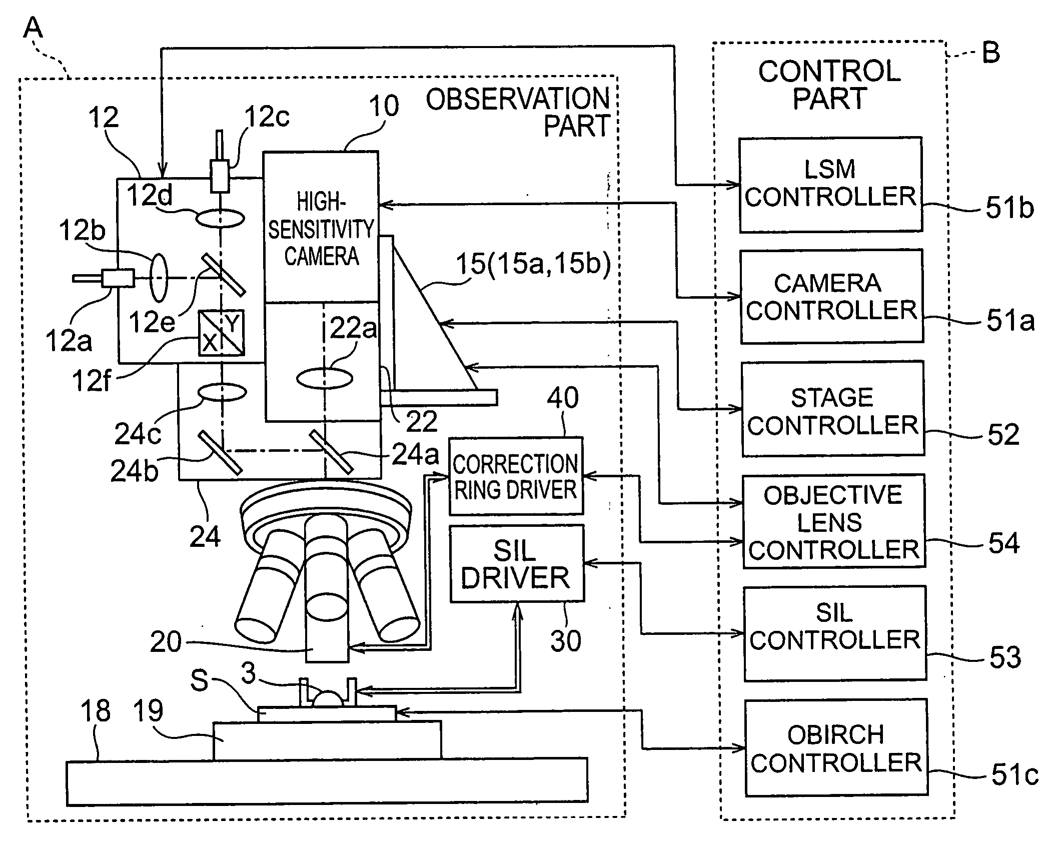
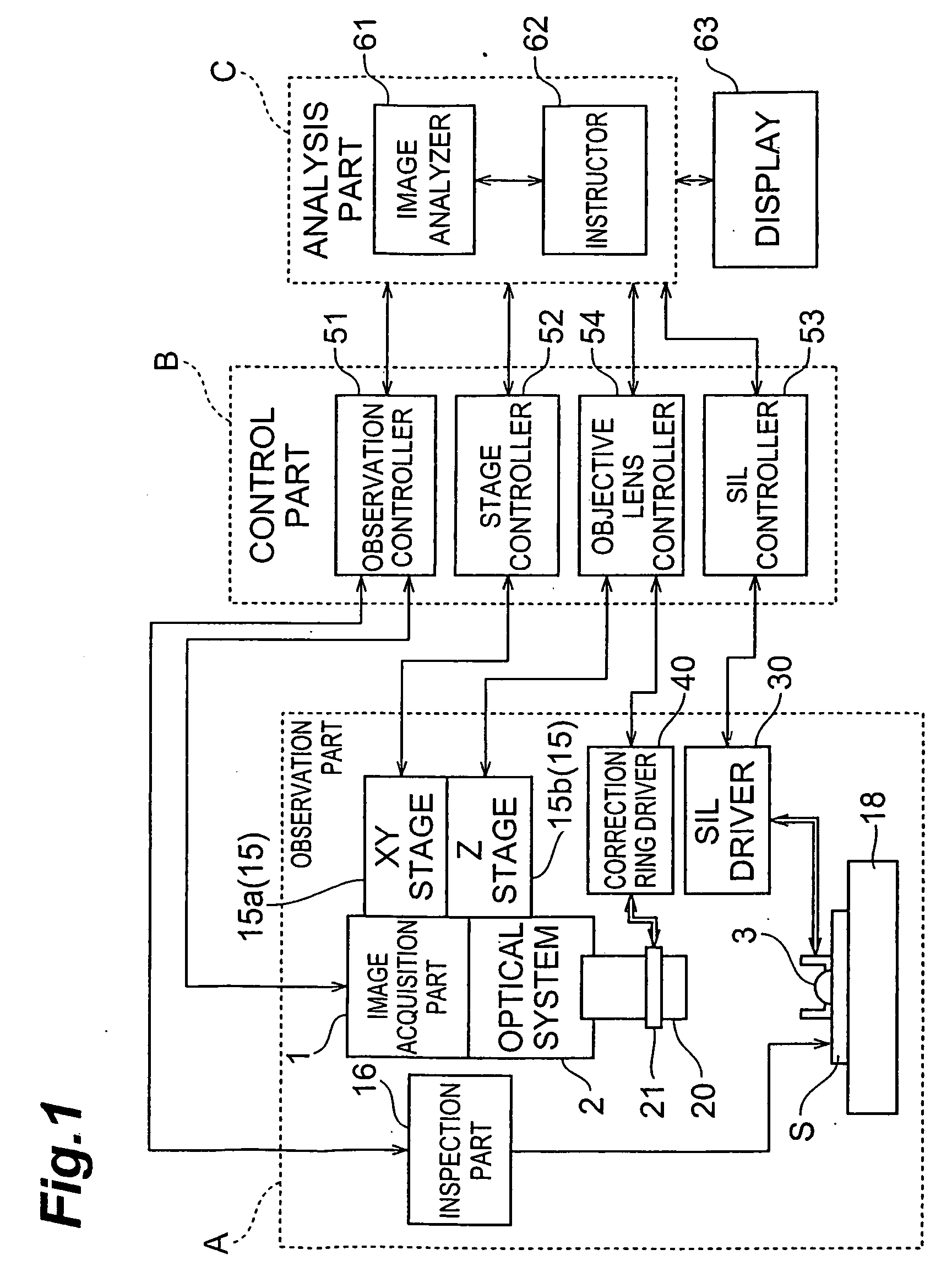
[0204]FIG. 21 is a configuration diagram showing a semiconductor inspection apparatus provided with the solid immersion lens holder according to the first embodiment of the present invention. FIG. 22 is a configuration diagram showing a configuration of the solid immersion lens holder. FIG. 23 is an exploded perspective view of the solid immersion lens holder. FIG. 24(a) is a sectional view along line IV-IV in FIG. 23, and FIG. 24(b) an enlarged view of an end portion of a lens holding part in the solid immersion lens holder shown in FIG. 24(a). FIG. 22 shows a state in observation of a sample while the solid immersion lens holder is mounted on an objective lens. FIGS. 23, 24(a), and 24(b) show a state in which the solid immersion lens holder holds a solid immersion lens. FIG. 24(b) shows a state in which the solid immersion lens is pressed against an observation object.

[0205] As shown in FIGS. 21 and 22, the semiconductor inspection apparatus 201 is, for example, a inspection devi...

second embodiment

[0247]FIG. 25 is a bottom view of solid immersion lens holder 208B according to the second embodiment. FIG. 25 shows a state in which the solid immersion lens holder 208B holds a solid immersion lens 206.

[0248] The configuration of the solid immersion lens holder 208B is different from the configuration of the solid immersion lens holder 208A shown in FIG. 23, in that the width of connecting parts 281, 281, 281 is narrowed in part in the extending direction of each connecting part 281 (i.e., in the radial directions of the base part 250). The solid immersion lens holder 208B will be described with focus on this point.

[0249] Since the width of the connecting parts 281 is narrowed in part, the connecting parts 281 will be broken if a predetermined stress is exerted through the solid immersion lens 206 or the like on the holding member 261.

[0250] Since the solid immersion lens 206 has to be brought into close contact with the semiconductor device 211 in order to observe the semicond...

third embodiment

[0256]FIG. 26 is a bottom view of solid immersion lens holder 208C according to the third embodiment. FIG. 26 shows a state in which the solid immersion lens holder 208C holds a solid immersion lens 206.

[0257] The configuration of the solid immersion lens holder 208C is different from the configuration of the solid immersion lens holder 208A shown in FIG. 23, in that the solid immersion lens holder 208C has three stress detection sensors S, S, S. The solid immersion lens holder 208C will be described with focus on this point.

[0258] A stress detection sensor S is stuck onto each connecting part 254 and detects the stress exerted through the lens holding part 260 on the connecting part 254 during observation of the semiconductor device 211, as described in the second embodiment. The stress detection sensors S can be, for example, strain gages.

[0259] The stress detection sensors S are electrically connected through the peripheral controller 233 to the instructor 242 (cf. FIG. 21), a...


PUM


Abstract

For a semiconductor device S as an inspected object, there are provided an image acquisition part 1, an optical system 2 including an objective lens 20, and a solid immersion lens (SIL) 3 movable between an insertion position including an optical axis from the semiconductor device S to the objective lens 20 and a standby position off the optical axis. Then observation is carried out in two control modes consisting of a first mode in which the SIL 3 is located at the standby position and in which focusing and aberration correction are carried out based on a refractive index n0 and a thickness t0 of a substrate of the semiconductor device S, and a second mode in which the SIL 3 is located at the insertion position and in which focusing and aberration correction are carried out based on the refractive index n0 and thickness t0 of the substrate, and a refractive index n1, a thickness d1, and a radius of curvature R1 of SIL 3. This provides a microscope and a sample observation method capable of readily performing observation of the sample necessary for an analysis of microstructure or the like of the semiconductor device.

Description

RELATED APPLICATION [0001] This is a Continuation-In-Part application of application Ser. No. 10 / 880,100 filed on Jun. 30, 2004, now pending.BACKGROUND OF THE INVENTION [0002] 1. Field of the Invention [0003] The present invention relates to a microscope used for observing a sample such as a semiconductor device at a predetermined observation plane and through the sample, and a sample observation method. [0004] 2. Related Background Art [0005] In recent years, many of semiconductor devices are being fabricated using face down bonding and flip chip bonding with a device surface (active circuit surface) at the bottom side of a substrate. In inspection of such semiconductor devices, it is sometimes difficult to expose the device surface of the substrate without disassembling a package, depending upon a type of the package and a mounting direction. Even in cases where a device surface of a substrate mounted not using the flip chip mounting can be exposed, but where semiconductor devices...

Claims


Application Information

Patent Timeline
IPC IPC(8): G02B21/00
CPCG01N21/9501G01N21/956G01N21/95684G02B21/0016G02B21/33G02B21/362
Inventor TERADA, HIROTOSHIARATA, IKUOTOKIWA, MASAHARUTANABE, HIROSHISAKAMOTO, SHIGERUISOBE, YOSHIO
Owner HAMAMATSU PHOTONICS KK
Why Eureka
Try Eureka