
Warning lamp

a technology of warning lamp and light beam, which is applied in the field of warning lamps, can solve the problems of reducing affecting the service life of the lamp, and achieve the effects of prolonging the service life, enhancing the effective of the warning lamp, and enhancing the light intensity of the beam emitted

Inactive Publication Date: 2006-08-10
A L LIGHTECH
View PDF14 Cites 44 Cited by
  • Summary
  • Abstract
  • Description
  • Claims
  • Application Information

AI Technical Summary

Benefits of technology

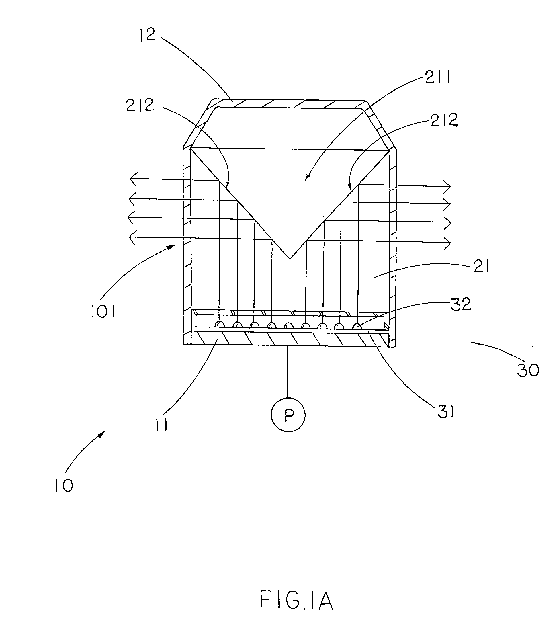
[0008] Another object of the present invention is to provide a warning lamp, wherein the converging element can substantially enhance the light intensity of the light beams emitted from the light source. In other words, the converging element converges the light beams emitted from the light source by total internal reflections such that no reflective coating is required.
[0009] Another object of the present invention is to provide a warning lamp, wherein the converging element embodies as a solid converging lens to guide the light beams to form collimated light beams by total internal reflections so as to substantially enhance the effective of the warning lamp and to prolong the service life span of the present invention.
[0010] Another object of the present invention is to provide a warning lamp, wherein the light source comprises a plurality of LEDs programmed to emit the light beams towards the diverging element such that no motor or driving rotor is needed to drive the converging element to rotate for producing flashing light effect. In other words, the warning lamp requires less mechanical component to not only minimize the malfunction of the warning lamp but also reduce the manufacturing cost of the warning lamp.
[0011] Another object of the present invention is to provide a warning lamp, which is simple in structure, easy to manufacture, convenient to use and does not involve complicated electronics, so as to minimize manufacturing and the ultimate selling price of the present invention.

Problems solved by technology

However, such warning lamp has several drawbacks.
However, the light is radially projected from each of the LEDs such that a portion of light is distracted from the respective LED before reaching the reflector so as to reduce the effective of the warning lamp.
Such reflector is fragile that when an external impact force is exerted on the light housing, the reflector would be broken in pieces by the vibration of the light housing.

Method used


Image

  • Warning lamp
  • Warning lamp
  • Warning lamp

Examples


Embodiment Construction

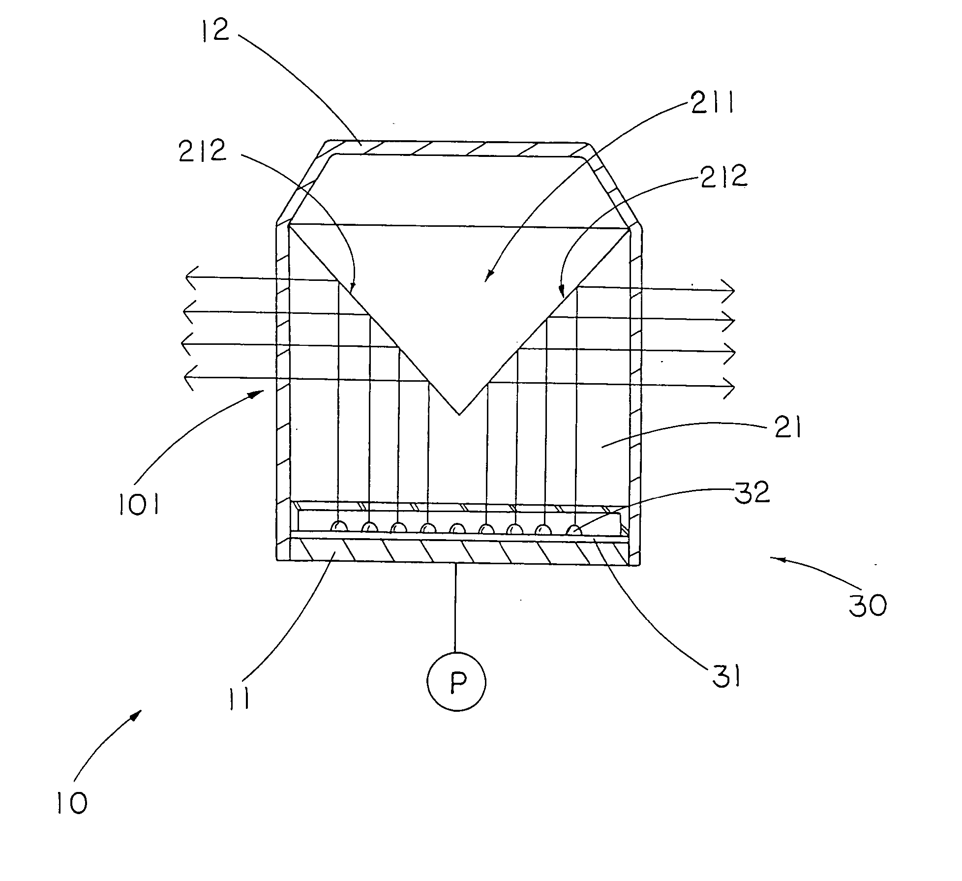
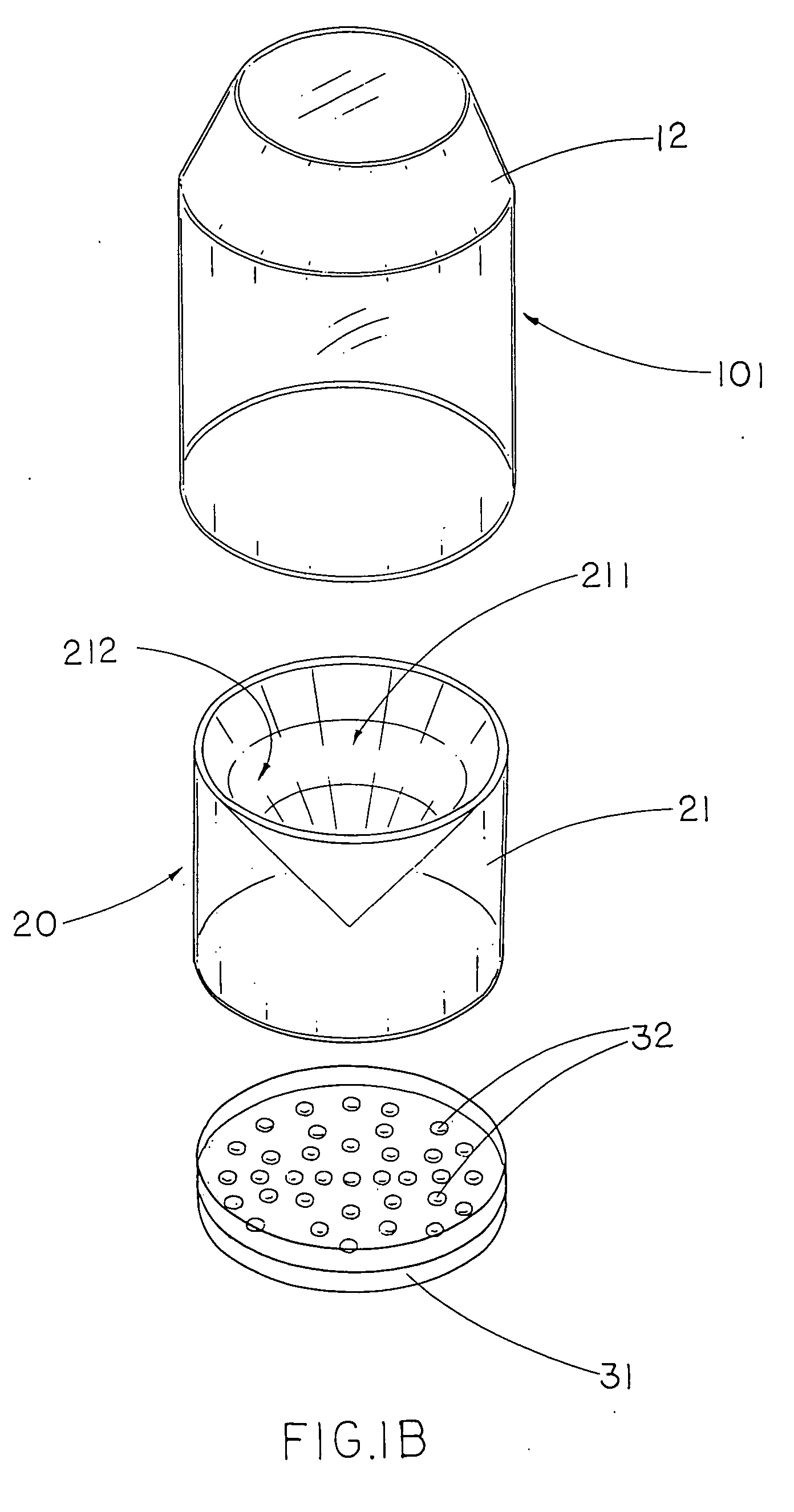
[0025] Referring to FIGS. 1A and 1B of the drawings, a warning lamp according to a first preferred embodiment of the present invention is illustrated, wherein the warning lamp comprises a light housing 10 having a light window 101, a converging element 20 supported in the light housing 10 at a position aligning with the light window 101, a high intensity light source arrangement 30, which is electrically connected to a power source P, for generating high intensity light beams towards the converging element 20, wherein the converging element 20 diverges the light beams to form collimated light beams so as to horizontally project out from the light window 101 of the light housing 10 in 360° direction.

[0026] According to the preferred embodiment, the light housing 10 comprises a supporting base 11 and a transparent shelter 12 forming the light window 101. The light housing 10 is made of light but durable material to protect the converging element 20 and the high intensity light source...


PUM


Abstract

A warning lamp includes a light housing having a light window, a converging element supported in the light housing at a position aligning with the light window, and a high intensity light source arrangement for generating high intensity light beams towards the converging element, wherein the converging element diverges the light beams to form collimated light beams so as to horizontally project out from the light window of the light housing in 360° direction.

Description

BACKGROUND OF THE PRESENT INVENTION [0001] 1. Field of Invention [0002] The present invention relates to a lighting fixture, and more particularly to a warning lamp comprising a converging element to diverge high-intensity light beams from a light source in 360° direction. [0003] 2. Description of Related Arts [0004] A conventional warning lamp are commonly used to indicate the existence of a hazardous situation, wherein the warning lamp comprises a light housing, a light source supported on a base of the light housing and a cone-shaped reflector supported above the light source and arranged in such a manner that when the light source upwardly projects light beams towards the reflector, the reflector reflects the upward light beams to collimated light beams as a warning signal so as to horizontally project out from the light housing in 360° direction. In order to enhance the warning signal, a motor or a driving rotor is mounted in the light housing to drive the reflector to rotate t...

Claims


Application Information

Patent Timeline
Patent Type & Authority Applications(United States)
IPC IPC(8): F21V3/00F21V5/00
CPCB60Q1/2611F21W2111/00F21Y2101/02F21Y2115/10
Inventor SHEN, PENN Q.ZHANG, LONG BAO
Owner A L LIGHTECH
Learn More