
Horizontal type orbiting vane compressor

Inactive Publication Date: 2006-08-10
LG ELECTRONICS INC
View PDF0 Cites 4 Cited by
  • Summary
  • Abstract
  • Description
  • Claims
  • Application Information

AI Technical Summary

Benefits of technology

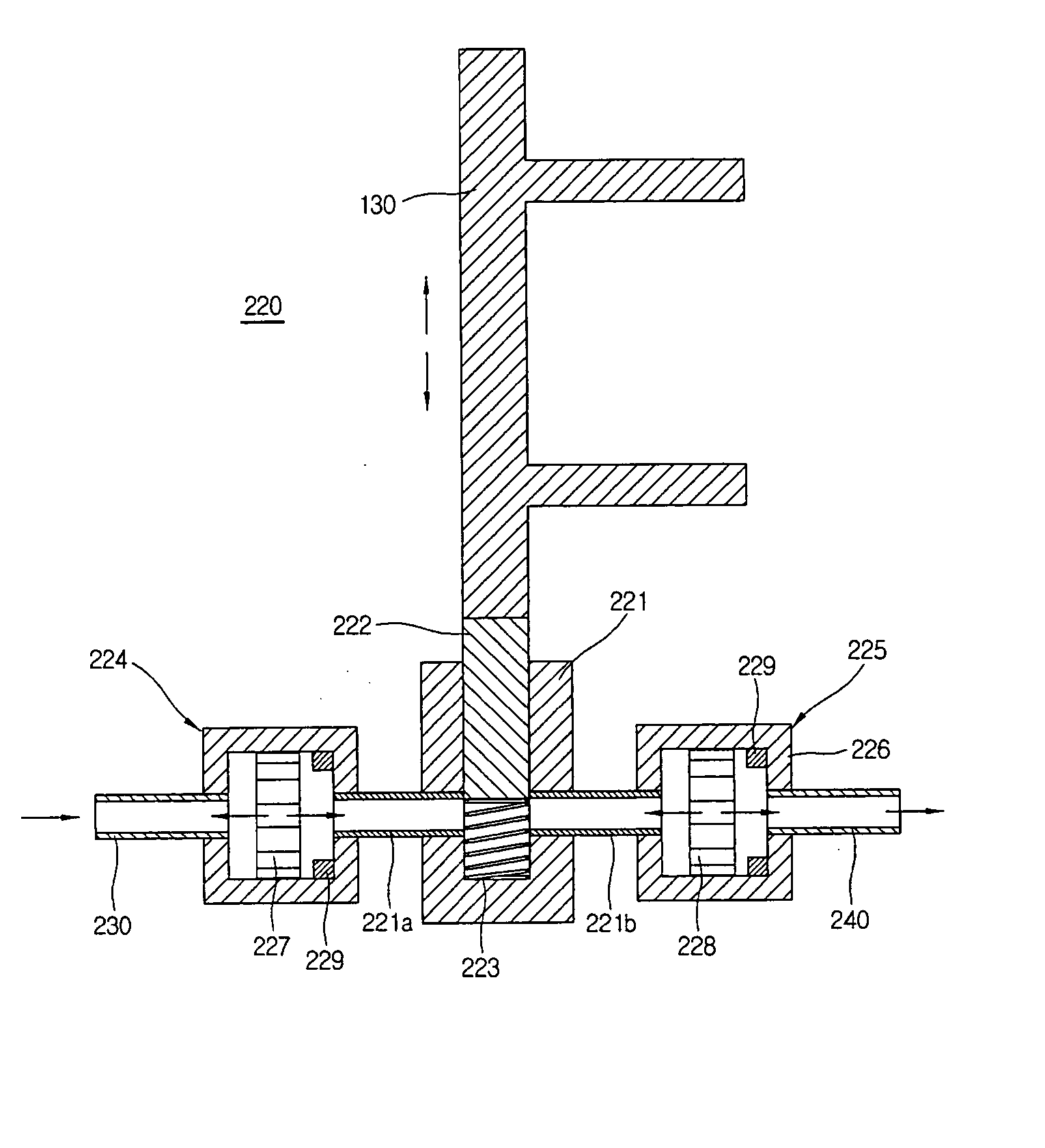
[0020] It is another object of the present invention to provide a horizontal type orbiting vane compressor that is capable of eliminating problems in connection with oil supply.
[0021] It is yet another object of the present invention to provide a horizontal type orbiting vane compressor that is capable of increasing the flow rate of oil through improvement of an oil-supplying structure.
[0032] Preferably, the oil-supplying unit further comprises: a propeller mounted at the entrance of the oil hole of the rotary shaft for increasing the flow rate of the oil supplied into the oil hole of the rotary shaft through the oil outlet tube.

Problems solved by technology

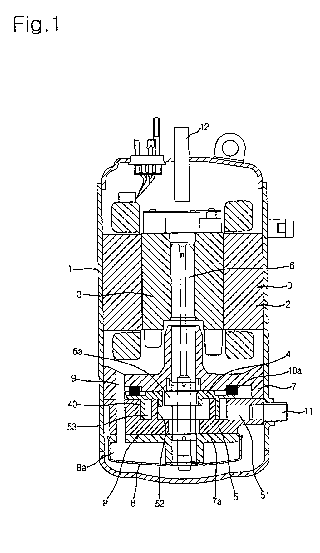
When the vertical type orbiting vane compressor is installed in an outdoor unit of an air conditioner, the size of the outdoor unit is relatively increased, since the vertical type orbiting vane compressor occupies a relatively large installation space in the outdoor unit, and therefore, miniaturization of the outdoor unit is very difficult.
However, serious consideration must be given to an oil-supplying structure of the horizontal type orbiting vane compressor when the horizontal type orbiting vane compressor is designed.

Method used


Image

  • Horizontal type orbiting vane compressor
  • Horizontal type orbiting vane compressor
  • Horizontal type orbiting vane compressor

Examples


Embodiment Construction

[0042] Now, a preferred embodiment of the present invention will be described in detail with reference to the accompanying drawings.

[0043]FIG. 3 is a longitudinal sectional view illustrating the overall structure of a horizontal type orbiting vane compressor according to the present invention. As shown in FIG. 3, the horizontal type orbiting vane compressor comprises: a hermetically sealed shell 100, which is horizontally disposed; a compression unit P disposed at one side in the shell 100; and a drive unit D disposed at the other side in the shell 100. The compression unit P and the drive unit D are connected to each other via a rotary shaft 150, which has an eccentric part 151.

[0044] The drive unit D comprises: a stator 110 fixedly disposed in the shell 100; and a rotor 120 disposed in the stator 110 for rotating the rotary shaft 150, which horizontally extends through the rotor 120, when electric current is supplied to the rotor 120.

[0045] The compression unit P comprises an o...


PUM


Abstract

Disclosed herein is a horizontal type orbiting vane compressor having a horizontal structure. The horizontal type orbiting vane compressor comprises a horizontally disposed shell having an inlet tube and an outlet tube, a compression unit disposed in the shell at one side of a horizontally disposed rotary shaft such that the compression unit is rotated by a drive unit for compressing refrigerant gas, and an oil-supplying unit for supplying oil from an oil sump to an oil hole extending through the rotary shaft by an orbiting movement of an orbiting vane in the compression unit. When the horizontal type orbiting vane compressor is applied to an air conditioner, an outdoor unit of the air conditioner is greatly reduced in size.

Description

BACKGROUND OF THE INVENTION [0001] 1. Field of the Invention [0002] The present invention relates to an orbiting vane compressor that is capable of forming compression chambers at the inside and the outside of a wrap of an orbiting vane as the wrap performs an orbiting movement in an operation space defined in a cylinder, and, more particularly, to a horizontal type orbiting vane compressor having a horizontal structure. [0003] 2. Description of the Related Art [0004] Generally, an orbiting vane compressor is constructed to compress refrigerant gas introduced into a cylinder through an orbiting movement of an orbiting vane in the cylinder having an inlet port. Various types of orbiting vane compressors, which are classified based on their shapes, have been proposed. [0005]FIG. 1 is a longitudinal sectional view illustrating the overall structure of a conventional rotary-type orbiting vane compressor. As shown in FIG. 1, a drive unit D and a compression unit P, which is disposed belo...

Claims


Application Information

Patent Timeline
IPC IPC(8): F01C20/18F16N13/20F01C1/02F04C2/00F04C14/18
CPCF04C23/008F04C29/025F04C18/344F04C29/02
Inventor HWANG, SEON-WOONGYOO, DONG-WON
Owner LG ELECTRONICS INC
Learn More